The world of smart electronics is brimming with exciting possibilities. But translating your ingenious concept into a tangible product requires navigating intricate complexities. A critical aspect lies in ensuring seamless integration between the electrical components on the circuit board (PCB) and the mechanical housing that encases them.
Traditionally, separate electrical and mechanical computer-aided design (ECAD & MCAD) software created potential hurdles during the validation stage. Imagine meticulously designing a complex PCB layout, only to discover during final assembly that it clashes with the enclosure.
The answer to these challenges lies in integrated MCAD/ECAD manufacturing, supported by a technology platform that gets your team (and your product design files) together early in the manufacturing process. By consolidating these functionalities into a unified platform, engineers can collaborate throughout the process, eliminating roadblocks and streamlining the journey from concept to production.
What is MCAD?
Mechanical engineers use the advanced software called Mechanical Computer-aided Design (MCAD) to create and modify the 2D and 3D geometry of their systems during development. This tool designs, models, and documents mechanical components, sheet metal components, assemblies, and products. Components can include molds, dies, and other tooling as well as the electrical PCB. MCAD provides many capabilities including:
The merging of both ECAD and MCAD allows virtual simulation of the manufacturing process.
- 3D Modeling. Create and modify designs using 3D geometry sets.
- 2D Sketching. Create and modify designs using 2D geometry sets.
- Assembly Modeling. 3D modeling capabilities built within set parameters and constraints.
- Engineering Documentation. This includes drawing views, 2D drafting sketches, and PMI dimensions and notes.
MCAD serves several purposes for validating new system mechanical aspects. Throughout the development process, MCAD software helps the engineering team explore different design versions, both in concept and in final detail. Different alternatives can be built within the tool and used to evaluate available options by comparing them against each other. The tool can also assess design form and fit options like weight or volume. This provides a check for mechanical interferences that can cause manufacturing issues later.
What is ECAD?
Electrical design and layout engineers use Electrical Computer-Aided Design (ECAD) to create schematic diagrams and printed circuit board (PCB) layouts. Outputs are both 2D and 3D designs assessing PCB electrical circuitry performance. ECAD provides many capabilities, including:
- Diagramming. Engineers can define components and the signals that connect them.
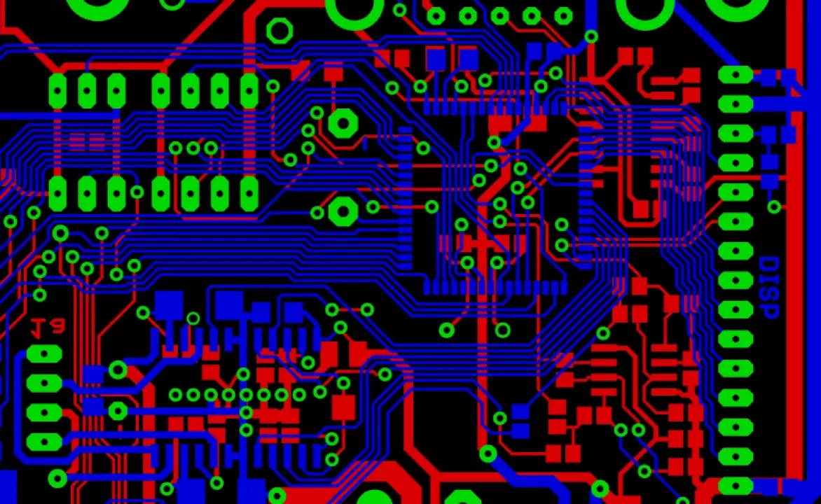
- Trace Routing. This defines the trace path between components within a specific PCB layer.
- 3D Assembly. This option provides 3D modeling capabilities.
- Collaboration. Team development capabilities capture and coordinate individual feedback.
- Concurrent Design. Multiple designs of the same PCB can happen simultaneously.
- Constraint Checking. ECAD automatically checks against the company or industry rules and highlights issues affecting performance or manufacturability.
- Export Capabilities. Generate ECAM design files and a BOM.
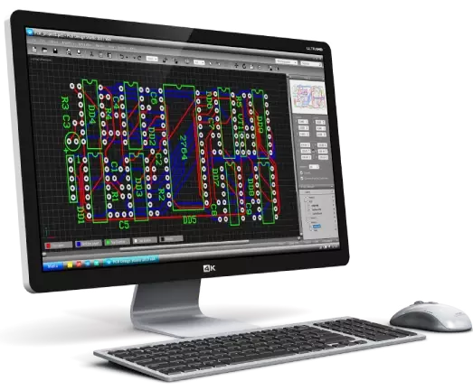
By changing components and attributes, ECAD software can explore complex electrical schematic iterations. This occurs as a schematic diagram in the abstract or in full layout detail using a 3D assembly library. Users can build out different layout alternatives and options with various component spacings, comparing them against the system’s electrical requirements.
As a final design step, ECAD software generates necessary manufacturing documentation. This documentation releases to manufacturing as part of the specification process used to source, fabricate, and produce PCB in high volumes.
The documented processes provide a method to add Product Manufacturing Information (PMI). PMI provides information such as dimensions and notes to a 3D electrical and mechanical model. Also, it provides bill of material (BOM) and assembly instructions to the factory for surface mounting technology (SMT) requirements for the components mounted on the PCB.
The Power of a Unified ECAD/MCAD Design Approach
Historically, CAD tools targeted electrical and mechanical functions separately. Two separate software packages were needed, or no interaction occurred between the two whatsoever. But as systems progressed in complexity, the interaction between electrical performance and mechanical design married as integrated functions.
Now proper component libraries allow both electrical and mechanical aspects of your system to be modeled in a single advanced software tool, such as Fusion. Mechanical modeling uses the mechanical aspects of each electrical component in two or three dimensions. This allows proper thermal and stress analysis of the entire system based on the spacing of the components within the enclosure.
This is the transformative power of integrated MCAD/ECAD. Here’s how it elevates your smart electronics design experience:
- Concurrent Design: Break free from the linear workflow. Electrical and mechanical design can occur simultaneously, significantly reducing overall design time. This parallel approach allows for faster iteration and exploration of design options, accelerating your time to market.
- Enhanced Communication: Say goodbye to communication gaps! With everyone working on the same platform, electrical and mechanical teams are on the same page, fostering a more efficient and collaborative design process. Misunderstandings due to separate design files and software are a thing of the past.
- Streamlined Documentation: Integrated MCAD/ECAD software generates comprehensive design documentation (including bills of materials and assembly instructions) directly from the 3D model. This eliminates errors caused by manual data entry and ensures a smooth manufacturing handover.
MacroFab: Your Partner in Integrated Design Success
At MacroFab, we champion seamless MCAD/ECAD integration. Our comprehensive platform empowers you to:
- Streamline Design and Manufacturing: Eliminate data transfer hassles. Our platform integrates seamlessly to take your design from concept to production with ease. This simplifies the workflow and reduces the potential for errors during data exchange.
- Boost Design Confidence: Leverage advanced features to thoroughly validate your design before it goes into production. Identify and fix potential issues early in the design cycle to reduce the risk of costly rework later.
- Benefit from Expert Support: Our account managers act as an extension of your team, providing clear communication channels and proactive support throughout the entire design and manufacturing journey. We offer more than just manufacturing; we provide the guidance and expertise to help you navigate the complexities of smart electronics design.
Conclusion
Complex system designs now need co-simulation of electrical and mechanical technical attributes. One single CAD tool such as Fusion, can now cover both ECAD and MCAD model simulation using advanced libraries, providing more detailed design validation for higher confidence in first article prototype success.
These sophisticated CAD tools also generate all the documentation needed for production processes to properly inform factories of manufacturing requirements. While new software packages seem daunting to a productive design team, your contract manufacturing (CM) partner should be part of your support team. With your CM partner’s assistance, these toolsets can assimilate into your design process with successful results.
Discover Why Engineers Prefer MacroFab
Download the Whitepaper “How to Avoid Electronics Manufacturing and Assembly Issues Using Integrated ECAD/MCAD”