Understanding the strengths and weaknesses of Surface-Mount Technology (SMT) and Through-Hole Technology (THT) is crucial for any Printed Circuit Board (PCB) designer or manufacturer. This blog post explores the key differences between these two PCB assembly methods to help you make the best choice for your next project.
SMT vs. Through-Hole Assembly: A Quick Overview
Surface Mount Technology (SMT) assembly is a technique where components are placed directly onto a printed circuit board (PCB). This efficient method leads to a densely packed yet lighter final product.
In contrast, through-hole assembly has been around for a while. Here, components are inserted into pre-drilled holes on the PCB and then wave-soldered from the bottom to fill the holes and establish the necessary interconnections. This difference, while seeming small, changes many things, such as the board design, the materials and processes used, heat dissipation, and associated labor and setup costs.
That’s where this guide comes in. It’s here to help you understand the difference between SMT and THT so you can choose the best method for your next project. Additionally, it offers some useful tips for designing SMT board designs to ensure they are easy to assemble.
Key Points
• SMT and THT as Complementary Approaches: Surface mount and through-hole components are often used together within a single product to leverage the strengths of each technology based on the requirements of the specific application. • SMT Design for Manufacturability: Designing for manufacturability involves considering aspects such as standard sizes and shapes, component selection, alignment and spacing, handling via holes, and designing for testability to ease production, reduce costs, and improve product quality. • Use Cases for THT: THT is preferred for high-stress mechanical applications, high power, and high-temperature applications, where reliability under these conditions is a necessity.
Understanding the Basics of SMT PCB Assembly
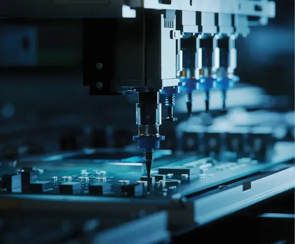
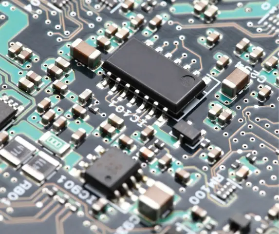
SMT assembly refers to the process of assembling electronics by mounting components directly onto the surface of printed circuit boards through a process known as batch solder reflow.
The process begins with the application of solder paste to the PCB. Subsequently, the components are strategically placed onto the board. The entire assembly is then heated in a controlled manner via a reflow oven. The heat causes the solder paste to melt, or ‘reflow,’ establishing a connection between the components and the PCB. After cooling, the solder solidifies, forming a robust bond between the components and the PCB.
SMT assembly is highly automated. This can significantly reduce labor costs for large production runs. However, this method may be less efficient for smaller operations. Moreover, skilled workers are needed for managing sophisticated equipment and for performing any required manual rework.
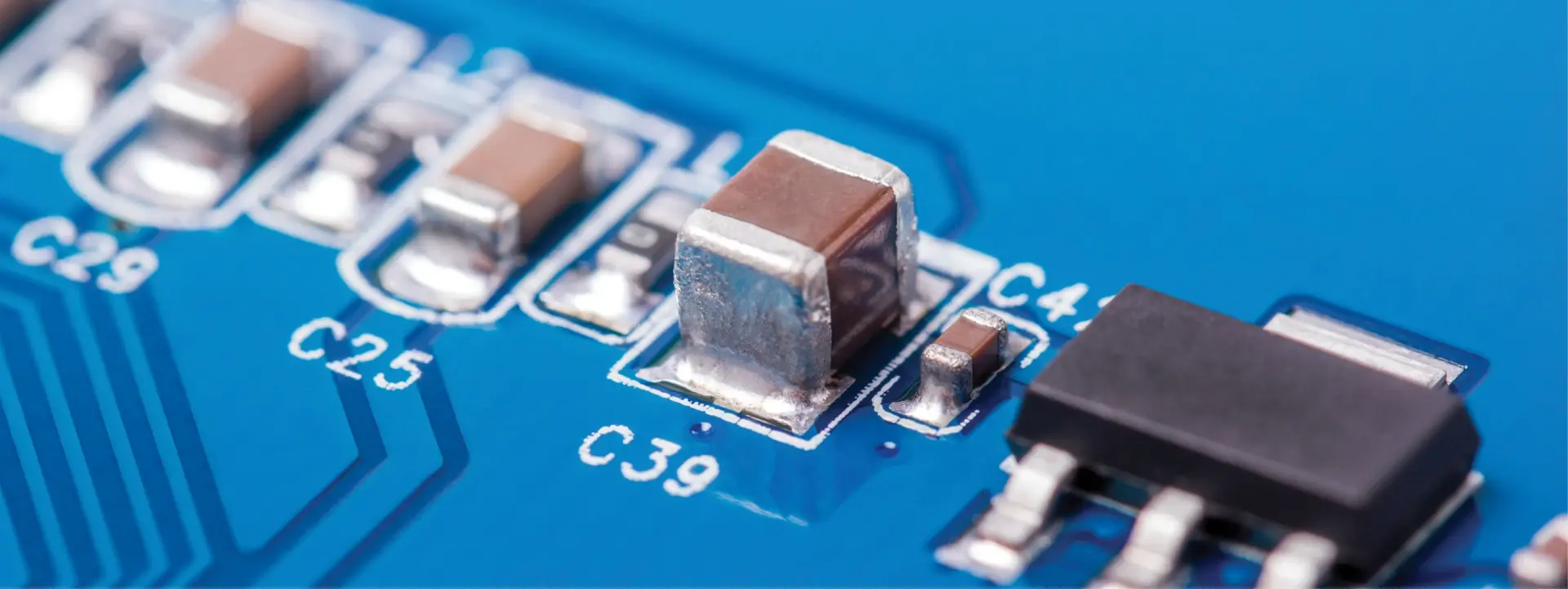
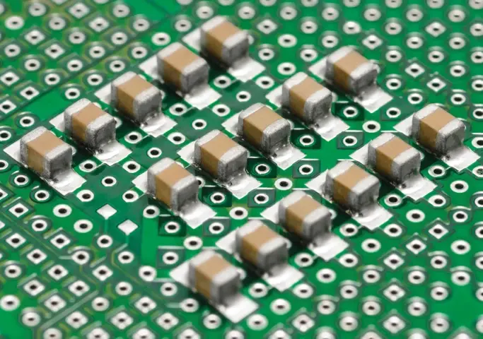
The components used in SMT are known as Surface-Mounted Devices (SMDs) or Surface-Mounted Components (SMCs). The term SMD is also used in electronics to refer to solder mask-defined pads. Unlike traditional components, SMDs have distinct packaging. Instead of wired leads, they possess small metal or ceramic contacts on their underside, enabling them to be soldered directly onto pads on the PCB. This unique packaging grants SMDs certain characteristics:
- They are smaller and much lighter than regular components.
- Their shorter lead lengths lead to lower inductance and capacitance, which can improve electrical performance.
- SMDs are more susceptible to moisture-related cracking.
There are three main types of SMT assembly:
- Type I: This type uses only SMDs. The components can be mounted on one side (single-sided) or both sides (double-sided) of the PCB.
- Type II: This type uses a mix of SMDs and through-hole components. It’s often used when certain components aren’t available as SMDs. This assembly type is the most complex to manufacture because it has many process steps.
- Type III: This type replaces only discrete components (like diodes or resistors) with their surface mount counterparts. Usually, these discrete surface mount components are fixed to the underside of the PCB, while THT components are placed on the top side.
Advantages of SMT Assembly
SMT assembly comes with several design and manufacturing benefits, such as:
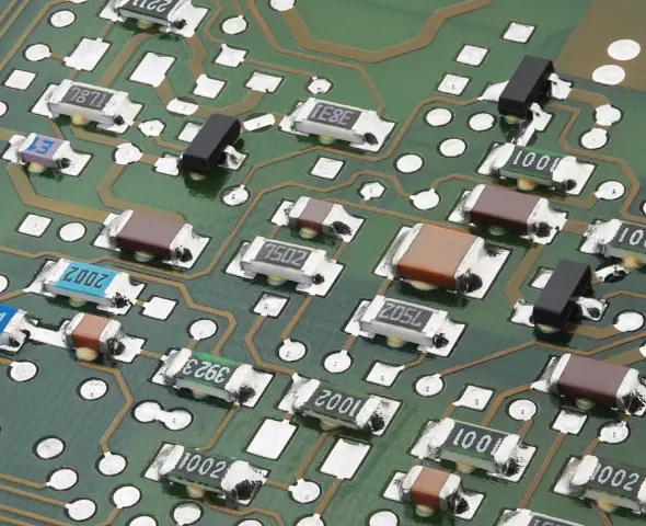
High Component Density: SMT assembly allows for more components per square inch of PCB real estate because SMD components are small and can be placed on both sides of the board. This facilitates more sophisticated circuit designs without enlarging the PCBA.
Weight Savings: SMT components can weigh up to ten times less than traditional counterparts. This weight reduction is particularly vital in aerospace and aviation, where weight reduction is key.
Improved Electrical Performance: Surface mount packages have lower parasitics (undesirable inductive and capacitive elements). This results in reduced propagation delays and reduced noise, and this improved electrical performance becomes even more significant and critical as clock speeds increase.
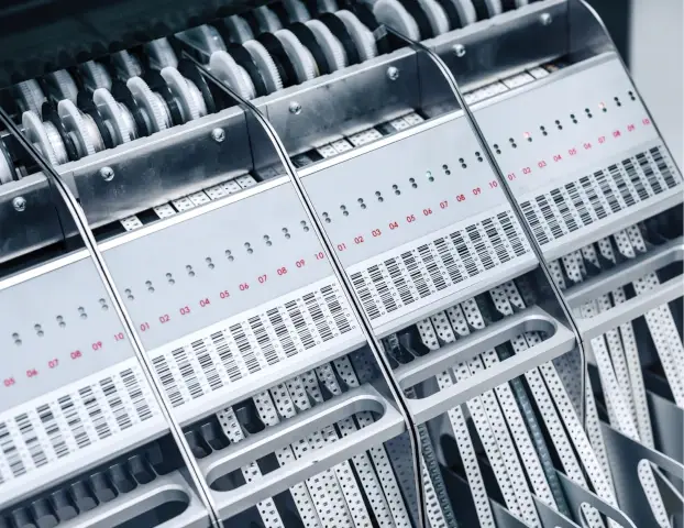
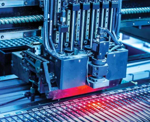
Easier Automation: SMT is highly compatible with automated assembly processes. Automated pick-and-place machines can place components faster and more accurately than humans, greatly speeding up the assembly process. This can help reduce the time required for prototyping and also improve scalability.
Cost Efficiency: SMT assembly can lower board costs due to reduced drilling. Fewer drilled holes also facilitate the routing of traces on the board.
Drawbacks of SMT Assembly
While SMT assembly has many advantages, there are several challenges to keep in mind:
Quality Control Challenges: Due to the high-speed, automated nature of surface mount assembly processes, assembly line problems can result in a large batch of faulty assemblies before the issue is detected, increasing waste. Working with modern manufacturers using digitized, connected processes can reduce this.
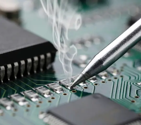
Difficulty in Repair or Replacement: The small size of surface mount components and the high density of SMT boards make them tricky to replace or repair. Furthermore, manual visual inspections are challenging, necessitating automated inspection equipment that raises overall production costs.
Reliance on Solder Joints: SMT relies more heavily on solder joints for both mechanical and electrical connections than through-hole technology does. Consequently, any flaw in these joints can undermine the assembly’s reliability.
Part Identification Difficulties: Surface mount components are smaller, often making clear markings challenging, especially on passive components. This can lead to problems if devices get mixed up. They would need to be positively identified or discarded.
Increased Thermal and Moisture Susceptibility: Surface mount packages encounter higher temperatures during soldering than through-hole components, potentially causing thermal stress if components aren’t adequately rated for these temperatures. Heat dissipation may become an issue when these closely-placed components are active. Also, certain types of SMT components can easily absorb moisture, which, when rapidly heated during soldering, can cause internal damage in a phenomenon known as “popcorning.”
Stringent Cleanliness Needs: Surface mount components are placed very close to the surface of the substrate, with less clearance than through-hole packages. This requires rigorous process control to ensure cleanliness and prevent contamination that might disrupt assembly and performance.
Determining the Suitability of Surface Mount Technology for Applications
Surface Mount Technology doesn’t serve as a universal solution for all circumstances. As with any technology, it excels in specific applications but may not be the optimal choice in others. So, when is it suitable to consider SMT for your projects?
High-Speed, High-Density Applications: SMT is particularly advantageous in situations requiring high-density electronic components. Such devices benefit significantly from the ability of SMT to fit more components onto a printed circuit board, including on both sides if necessary.
Lightweight, Compact Devices: Using SMT components reduces the overall device’s weight and size. This is advantageous for applications where weight and form factor matter, such as aerospace applications, drones, and portable devices.
High-Volume, Low-Cost Production: From the standpoint of electronics manufacturing, SMT assembly lines deliver speed and precision. The involved automation can drastically curtail production time, allowing for the efficient manufacture of high volumes finished boards. In the case of mass-produced devices where cost-effectiveness is paramount, SMT offers substantial benefits.
Reliability and Performance-Driven Applications: Smaller components and shorter signal paths in SMT assemblies can lead to improved speed and signal quality performance. Also, the reduced need for drilled holes can augment the structural integrity of the finished assembly, contributing to its reliability.
Nevertheless, SMT might not always be the best choice. SMT heavily depends on automated machinery, making it less suitable for manual assembly scenarios or individual prototype developments. For hobbyists or within a prototyping context, Through-Hole Technology might be more convenient due to its compatibility with manual assembly techniques.
The Power of Through Hole Assembly
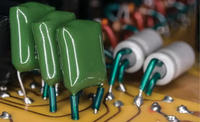
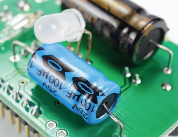
Through-Hole Technology is another component assembly technology. Its name originates from how it’s done: component leads are threaded through holes drilled into the circuit board and then soldered to pads on the other side. While THT was the original standard for assembling PCBAs, it continues to be essential in the electronics industry despite the advent of Surface Mount Technology.
Through-Hole Technology Assembly Process
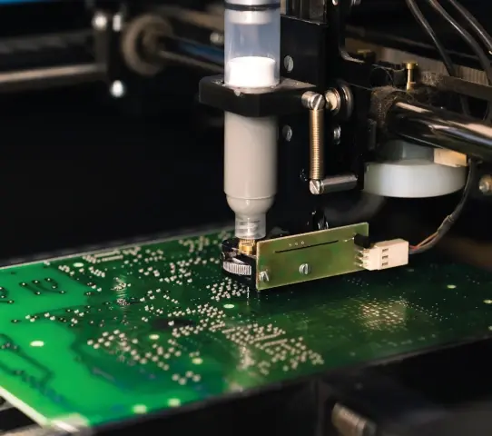
THT assembly starts by drilling precise holes into the PCB. These holes match the specifications of the components that will be attached. Leads from the THT components are inserted into these holes, preparing them for the soldering process. The soldering can be done via wave soldering or selective soldering methods. Both aim to create a robust physical and electrical bond between the lead and the PCB assembly by filling the hole with molten solder.
Wave soldering involves the PCBA passing over a reservoir of molten solder. A pump creates a ‘wave’ of this solder, which contacts and adheres to the PCBA, soldering the components in place. On the other hand, selective soldering specifically targets areas on the PCBA that need soldering. This precise method bypasses the need for solder masks, depositing the solder only where necessary on the board.
Listen to this classic episode of Circuit Break to learn more about Through Hole Manufacturing.
Advantages of Through-Hole Technology
Despite the prevalence of newer surface mount technology, THT still retains several unique benefits that underscore its enduring relevance.
Strong Component Connections: THT components are held in place by physical leads that pass through the board and are soldered on the other side. This creates a robust connection that is resistant to mechanical stress, making THT an excellent choice for components that will be subjected to physical strain, such as connectors, switches, or large, heavy components.
Despite the prevalence of newer surface mount technology, THT still retains several unique benefits that underscore its enduring relevance.
Reliable Performance under High Temperatures: THT components are generally better at withstanding extreme thermal environments. This is advantageous for applications operating in high-temperature environments or undergoing significant thermal cycling.
Ease of Prototyping and Debugging: THT components are generally easier to work with for manual assembly, prototyping, or testing. They can be manually inserted and soldered, facilitating easy debugging or modification of prototypes.
Enhanced Testability: THT-designed boards inherently offer superior testability. The lead ends of the devices in through-hole boards also act as test nodes. This allows for efficient in-circuit testing as they can be easily accessed by test probes from the bottom side. This makes diagnosing and fixing any potential issues simpler and more efficient.
Limitations of Through-Hole Technology
While THT provides a number of advantages, it also comes with certain limitations that are important to consider.
Increased PCB Size and Cost: THT requires the drilling of holes into the PCBA, leading to an increased board size and associated costs. The drilling process also contributes to the total production time.
Lower Component Density: Because of the need for drilled holes and the size of the components, THT cannot match the component density offered by Surface Mount Technology, limiting its potential for miniaturization.
Difficulty with Fine Pitch Components: THT is not capable of handling components with tiny leads or closely-spaced leads (fine pitch components), thus limiting its compatibility with some modern electronic components. However, they remain necessary for some applications (see below.)
Applications and Use Cases for Through-Hole Technology
While SMT has taken over most of the PCB assembly process due to its suitability for miniaturization and automation, there are still several instances where THT is the preferred choice.
High-Stress Mechanical Applications: Applications where the PCBA will undergo a lot of physical stress, such as industrial machinery, would benefit from the strong physical connections of THT. They’re also suitable for industries such as aerospace, automotive, or military where vibrations, accelerations, and extreme temperatures are common.
High Power and High-Temperature Applications: For applications dealing with high power levels or high thermal environments, THT’s reliability under these conditions makes it an ideal choice.
Harmonizing SMT and THT: A Complementary Approach
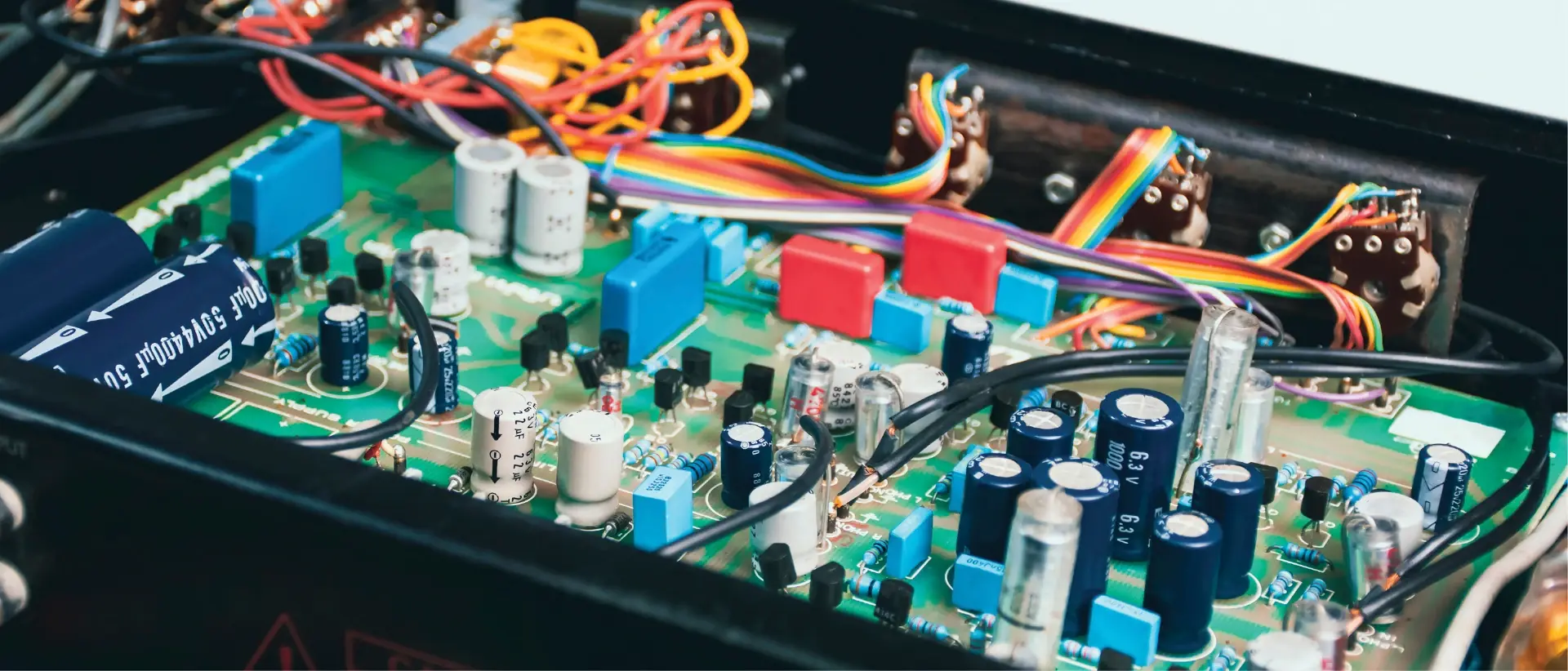
While SMT and THT are often discussed as distinct or competing assembly methods, it is important to note that they are not mutually exclusive. Instead, they are often used together within a single product to leverage the strengths of each technology.
In many electronic assemblies, it is not uncommon to find both THT and SMT components. The decision of which to use where is often driven by the requirements of the specific application, component availability, and the characteristics and limitations of the assembly processes.
For example, a memory board can be configured with Dual In-line Package (DIP) memory devices using THT on the upper side and SMT capacitors on the bottom. In this mixed technology setup, there will be less unwanted electrical noise than when using THT for everything. And because of the noise reduction, fewer decoupling capacitors would be needed for effective decoupling.
This complementary approach allows the designer to harness both technologies’ strengths to meet diverse design and performance requirements.
SMT Design For Manufacturability
Designing a board that’s hard to manufacture, fix, or test can cost a lot of money. To prevent that, it’s important to design with manufacturability in mind. This means creating a design that can be produced cost-effectively, is of good quality, and can be brought to market quickly. A well-designed board needs fewer iterations, cuts down labor and material costs, and shortens production time.
Here are a few tips to help you achieve this:
- Stick to standard sizes and shapes: By using standard PCB form factors, you can leverage existing manufacturing infrastructure and minimize the need for manual setups. This approach shortens production times and decreases overall costs.
- Select components wisely: Always opt for surface mount components that economize on space or simplify the manufacturing process. An SMD should be capable of automatic placement and withstand the anticipated reflow soldering temperatures. Components with solder plating terminations are preferred as they facilitate accurate centering during placement.
- Avoid unmarked SMD components: Components without markings can lead to mix-ups and problems during field repair. Thus, go for marked components whenever possible unless there’s a significant cost difference, or unless you have another reason for using them (for example, protecting your design from reverse engineering.)
- Use qualified components: Stick to components that are tested and proven to withstand your manufacturing processes. This will help avoid potential issues during production and service.
- Limit variety: By minimizing the number of distinct component types, the process of creating standard land patterns is streamlined, and vendor management complexity reduced. This approach minimizes the number of machine stops, reel switches, and the waste of unused components left on a reel, which can have a significant and direct impact on cost.
- Align and space components properly: Try to align similar components in the same orientation and maintain sufficient inter-package spacing between them. Uniform component placement helps with inspection, soldering, and testing. And, a minimum inter-package spacing is required to satisfy the various manufacturing requirements
- Carefully handle via holes: Avoid placing via holes within surface mount pads. This helps ensure a sufficient solder fillet during reflow soldering. If vias must be placed within a pad, they should be filled by the board fabricator.
- Design for testability: To ensure effective testing, all unused pins should be connected to Ground or Power through a resistor. Double-sided test probing should be avoided to cut down on fixturing and testing expenses. Implement one test point (TP) for Ground and one TP for Power for every 10 ICs to minimize the risk of ringing.
By adopting these strategies, you can design a product that is easier to manufacture, thereby reducing cost and time to market, and increasing the overall quality and reliability of your product.
Conclusion
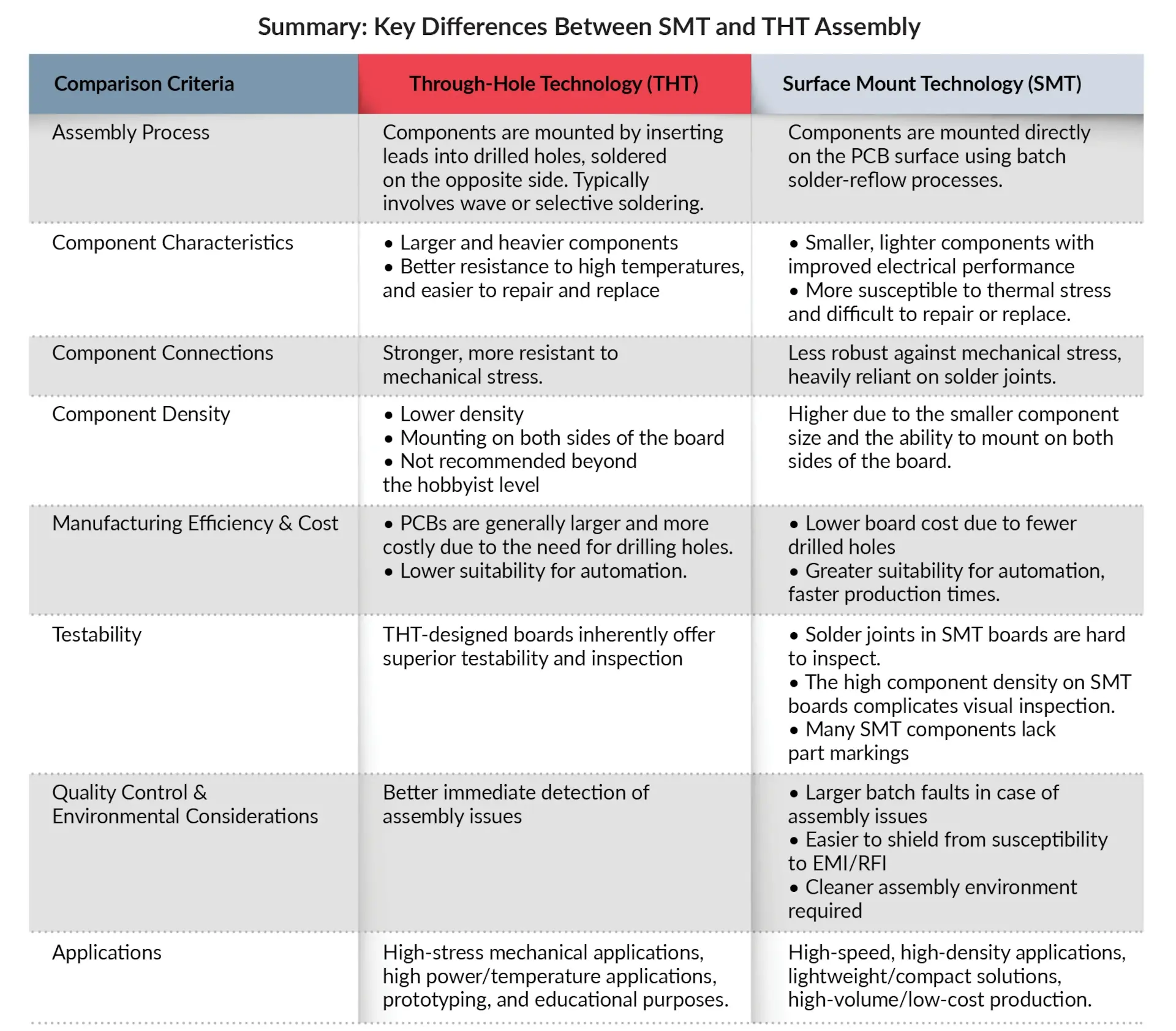
The choice between SMT assembly and THT assembly depends on various factors and requirements. SMT assembly offers advantages such as high component density, weight savings, improved electrical performance, easier automation, and cost efficiency. However, it also presents challenges in quality control, repairability, part identification, thermal and moisture susceptibility, and cleanliness requirements.
On the other hand, THT provides strong component connections, reliable performance under high temperatures, ease of prototyping and debugging, and enhanced testability. It does have limitations in terms of increased PCBA size and cost, lower component density, and inability to handle fine-pitch components.
The selection of the assembly method should consider the specific application’s needs, including high-speed/high-density requirements, lightweight and compact solutions, high-volume production, reliability, and performance demands, as well as manual assembly or prototyping scenarios.
Both SMT and through-hole assembly have their place in the electronics industry, and understanding their strengths and limitations is crucial in making an informed decision for each project.
Tap Into All of MacroFab’s Production Capabilities