MacroFab Blog
All components, electrical, mechanical, and functional will have some tolerance to consider.
System Tolerance Stack-Up for Production
Electrical and mechanical components are not absolute in their attributes. They have production tolerances within the design with variance over their manufacturing life that must be considered for a system design. All components, electrical, mechanical, and functional will have some tolerance to consider. For the design team, it is key to consider how important this will be for the system design. If neglected, it is possible that there will be cases where the system manufacturing or operation fails.
Plan for Variance
During the product design stage, a tolerance stack-up review should be part of any robust development. Components and part selection should not be chosen based only on functional use, cost, and performance within the design. The expected attribute variance over the manufacturing life must also be part of the decision process for their design-in use. Determine the expected tolerance variance from suppliers and vendors during the design stage. Mathematically test these against the requirements of the design to see if there will be violations within the system.
Consider the impact of the total variance against the cost and performance during the design stage. A lower-cost component may come with the unwanted side-effect of wider tolerances and less manufacturing control. Identify the tolerance requirement limits where manufacturing or performance of the final system are adversely impacted. If any can be found, then determine where the issue would first be identified. If it is with the end-customer, it is of course a non-starter. But, a manufacturing line-down situation could also result if a tolerance stack-up problem is not detected until components are in the process of assembly.
Tolerance Analysis
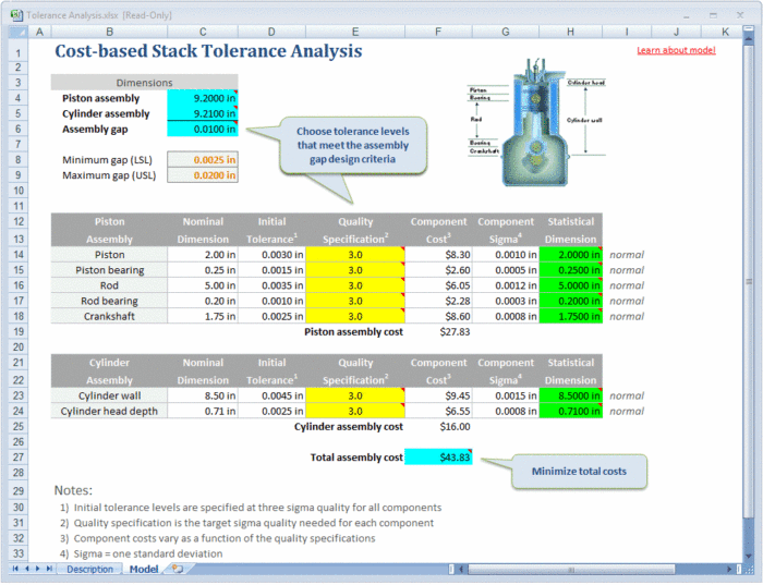
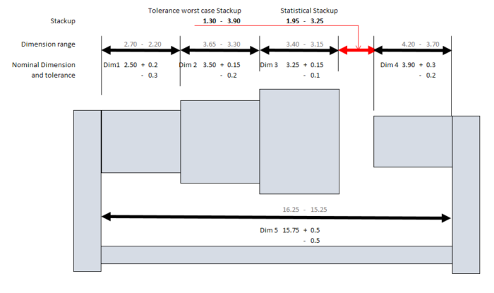
For a tolerance analysis, identify stack-up conditions where multiple component variances sum together for a violation of system limits. A quick worst-case tolerance check against a summation of absolute minimum and maximum tolerances can be a starting point. However, in most cases, this can be too conservative. While possible, it is statistically unlikely that the worst-case tolerance conditions will occur on multiple components from different lots of materials from different vendors.
A more balanced approach is to use a general statistical tolerance analysis by means of a root mean square error (RMSE) comparison. The RMSE model comprises the sum of the squares of all the worst-case tolerances. Then, the square root of this value is taken for the statistical worst-case tolerance. In Excel, the analysis for a three-component tolerance error (Ern) stack-up contribution would look something like this:=SQRT(SUMSQ(ErA + ErB + ErB)). For example, using the min/max stack-up of tolerances 2, 4, 6 would compute to a total error of 12. Using the RMSE approach, the statistical worst case would be sqrt(56) = 7.48.
A more sophisticated model comprises a compute-intensive Monte Carlo simulation. This method uses an algorithmthat relies on a repeated experiment usingrandom sampling to obtain numerical results. The underlying principle uses randomness to solve the tolerance problem and generates a probability distributionof outcomes. The more sampling that is done, the more accurate the distribution information will be for decisions. Depending upon how complex or simplistic your tolerance stack-up is for your system, this method may be excessive.
Testing and Mitigation
Once the worst-case tolerance scenarios are determined, use mitigation strategies for tolerance variance to minimize manufacturing or performance issues with the system before components arrive for assembly. First, establish those parameters that are guaranteed by the vendor’s design or their manufacturing processes. Second, investigate any vendor component testing that is done before shipment. If this is not listed on a datasheet, find out the tested performance limits and what is the typical distribution of the outgoing population. This distribution cannot always be assumed to be normal. Third, leverage your CM expertise in broad manufacturing for access to a wide array of the best distribution vendors. By using your CM’s kitting network, you may identify alternate components with tighter manufacturing tolerances than otherwise planned internally.
When possible, track vendor manufacturing component conformance using incoming inspection, electrical test, or other available parametric data. Many contract manufacturers can provide incoming visual inspection prior to assembly for mechanical dimensions. Work with your CM to determine the incoming testing and visual inspection options. Identify what components should be tested for incoming inspection. Agree with your CM what the acceptable tolerance deviation limits will be for those components in your system. Cull out the unwanted components outside these process limits to prevent them from inclusion in your assembly population. This will help prevent stack-up tolerance problems from getting into your manufacturing line. This can be evaluated during the initial prototype builds for your system ahead of production release.
Final testing of your complete system will ensure proper operation, free from tolerance stack-up issues. If the other mitigation strategies cannot identify tolerance errors, this is the last step in the process to find problems before being sent to the customer. While not preferred, any final test failures due to tolerance should have an iterative loop to close by using incoming CM inspections to push the failure identification back in the manufacturing process as early as possible.
Related Topics
How MacroFab Uses Clear Communication to Improve Your PCB Production Experience
This blog will discuss how MacroFab can help customers in their PCB production experience through clear communication in a high-octane environment.
Improve Your Next PCB Prototype: Better Debugging, Testing, and Reliability
Learn how to improve your next PCB prototypes as engineers push the boundaries of hardware technology to enhance debugging, testing, and general liability
Creating an Accelerated PCBA Lifecycle: From NPI to Production
Foster open communication to better embrace flexible BoM management and drive efficiency, quality, and innovation.
Standard and Custom PCB Layer Stackups
No matter the complexity of your PCBA, get the perfect stackup to meet your needs.
About MacroFab
MacroFab offers comprehensive manufacturing solutions, from your smallest prototyping orders to your largest production needs. Our factory network locations are strategically located across North America, ensuring that we have the flexibility to provide capacity when and where you need it most.
Experience the future of EMS manufacturing with our state-of-the-art technology platform and cutting-edge digital supply chain solutions. At MacroFab, we ensure that your electronics are produced faster, more efficiently, and with fewer logistic problems than ever before.
Take advantage of AI-enabled sourcing opportunities and employ expert teams who are connected through a user-friendly technology platform. Discover how streamlined electronics manufacturing can benefit your business by contacting us today.

