RF systems are most vulnerable to antenna design errors.

RF systems have different challenges to overcome than DC or low-speed systems. High-speed RF signals, for use in radios, need special attention to higher-order electrical engineering principles. PCBA materials and design architecture get scrutinized to meet the objectives of the system.
When supporting several radios or bandwidths of interest, cross- talk considerations need to be understood with frequency planning as a beginning step during the design. Planning for regulatory approvals requires an understanding of what constitutes a passing condition versus a failing condition.
Antenna Design
RF systems are most vulnerable to antenna design errors. While custom antennas can be designed by sophisticated RF engineers, most designers use readily available commercial RF antennas whenever possible, and targeted frequency chip antennas are available as commercial off-the-shelf (COTS) components.
However, when circuits are compressed, off-the-shelf components may not work due to space constraints. This is often the case in handheld and mobile products where COTS components won’t work.
Meanwhile, 5G and IoT are driving much of the demand for handheld and mobile devices. This has significant implications for RF performance, as such devices require higher data rates, lower latency, and improved efficiency. COTS antennas may not work well in the higher frequency bands used by 5G, nor are they efficient enough to meet the requirements of newer devices with tighter power constraints.
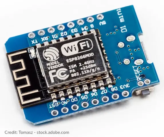
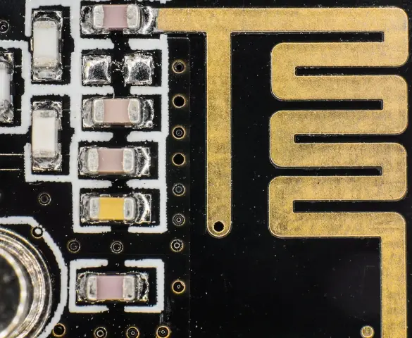
The goal of the antenna is to minimize the introduction of noise in the signal and maximize transmission and received signal gains while minimizing signal loss. System-on-chip (SOC) devices today that offer integrated radios and antennas can provide a solution if PCBA designers can integrate them into existing designs.
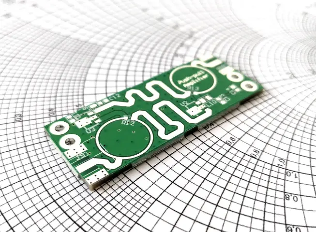
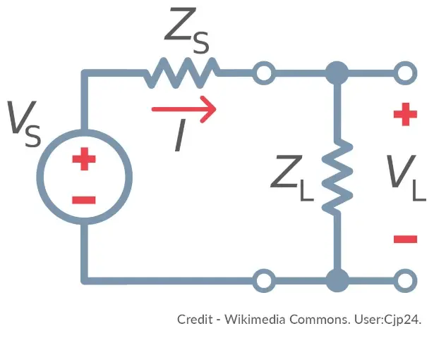
While most common transmission lines at lower frequencies are 50 ohms, a microstrip line can get tuned for any required impedance matching with the antenna, from many thousand ohms to a few ohms. Matching antenna impedance to its source will minimize RF signal loss, without reflections that create standing wave ratio (SWR) distortion.
Learn more about RF design, FCC pre-certification, and other field testing; listen to Circuit Break Podcast #182 now.
Power Distribution
Proper power distribution is crucial for optimal system performance. Voltage drop can occur along a trace when power is transferred from the source. A large power plane should be used instead of narrow power signal traces to minimize this effect.
Design your power traces as wide as possible to lower their impedance per square in ohms. Use proper decoupling capacitance to prevent unwanted high-frequency noise and low-frequency drops caused by amplifiers turning on and off to conserve power.

RF Front-end Design
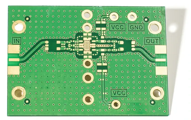
While the high-frequency carrier signal will be received at the antenna, the superheterodyne radio architecture will strip that signal with a mixer to retrieve the demodulated output signal of interest. A local oscillator drives a mixer to retrieve the usable signal. Proper RF front-end design uses a filter, amplifier, and signal processing to retrieve the signal without the introduction of noise or distortion.
The bandwidth of the filtering and signal chain processing must be a broad enough response to pass all the necessary signal sidebands to avoid distortion. However, it must be sufficiently narrow to prevent cross-talk of other radio signals and folding of their harmonics into the band of interest for that signal chain.
Additionally, as RF systems continue to increase in complexity, PCBA designers must determine how to fit all filters, amplifiers, and antennas into a limited amount of space. This is to ensure the desired performance. All of this must be accomplished while maintaining the device’s overall power requirements, preventing unwanted interference with other components, and preventing thermal runaway. Make sure to work with your contract manufacturing partner to determine the best practices for RF chain processing.
Frequency Planning
The purpose of radio frequency planning is to deliberate the frequency bandwidth for all the relevant signals across all the system radios. In addition to planning the carrier frequencies, the demodulated frequencies after down-conversion must be planned as well.
The harmonics (multiples of the primary frequency) should be planned as well since ‘frequency folding’ as 2nd and 3rd harmonics have the potential to also impact the RF design with unwanted cross-coupling to other signal chains. By planning out the frequencies of interest, bandwidths, and the secondary effects of harmonics, the RF design can be properly planned to support the intentional signal chains.
Signal Integrity
Transmission line impedance matching is critical for proper RF signal integrity. Since RF transmission line techniques such as microstrip and waveguides may be used, these can have various impedance ranges that match the source and receiver within the transmission line. Any design imperfections that cause a mismatch in impedance matching within the line could cause a loss of signal due to an SWR or reflections that steal signal power.
RF signal chains also require proper shielding from outside RF signals that could interfere with the processing. Intentional ground path vias are often used along a stripline path to prevent unwanted ground path returns by the signal. Metal shielding is often used to isolate the signal chain from the outside world of other RF signals that could be received.
Exotic PCBA Material
In PCBA manufacturing, FR4 is a common and widely used dielectric material. It can accommodate frequencies up to 3GHz without concern for loss or degradation of RF signal content.
However, designing for frequencies about 3GHz requires extra attention to signal fidelity and loss mitigation. While RF engineers may be able to use FR4 in creative ways for RF system design, the laws of physics work against the material for higher RF frequencies.
To achieve high performance in RF designs, it may be necessary to use exotic PCBA materials that can prevent signal attenuation and degradation. However, these materials can be more expensive than FR4. It’s important to consult with your CM partner for recommendations based on your specific RF performance needs.
Regulatory Approvals
All RF systems will either receive or transmit RF signals. Those with single or multiple radios will intentionally receive and transmit signals within certain known frequency bands. To limit the system to certain frequencies and power transmission, regulations are enforced by technical committees in various countries and regions globally. For example, within the USA, this governing body is the federal communications commission (FCC).
Challenges are inevitable when it comes to passing regulatory requirements. Each committee may have unique regulations, but all are intended to restrict the maximum permitted radio power parameters and regulate the use of frequencies that are either licensed or unlicensed.
Passing these requirements, however, may result in multiple redesigns to fix noise problems or other failures. Some designers circumvent this by beginning the design process using multi-path designs or dual-footprint components. These options provide fallbacks if the first design fails to meet requirements.
In addition, unintentional radiation of signals will be tested to ensure that the system does not harm other frequencies that are outside of its intentional use.
A product must be certified by these governing bodies to ensure that it complies with the regulations of the region where it will be sold. Work with your contract manufacturing partner to help with the RF regulatory approvals for your system.
There are many aspects of RF system design attributed to higher frequencies, which are not normally considered in low-frequency designs. Designing power distribution networks using wide traces that mitigate voltage drops and noise is important to maintain fidelity.

Use the appropriate prepreg materials for your PCBA to maintain high-frequency power. Frequency planning is important for the frequencies supported and their secondary effects on the system. Antenna selection is important for the radios of interest with most design engineers using COTS antennas. Shielding RF chains is important for signal integrity. The RF system gets designed with the intention of passing regulatory approvals for intentional and unintentional radiators.
By working with your CM partner for the best manufacturing decisions during the design of your manufacturing plan, your RF design has the maximum chance of first prototype success.

Build better with MacroFab