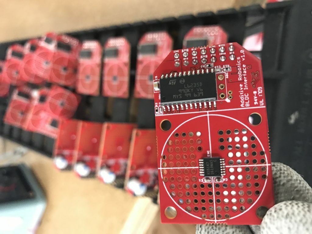
This week’s featured PCB comes from Additive Robotics and is an integrated interface for brushless DC (BLDC) motors. The board basically allows you to control, sense, and cool an attached motor, in a way that is very efficient in terms of form factor, weight, and power.
The board was developed for use in high-end educational robotics kits, for Huston-Tillotson University (HTU). The board (and supporting hardware) will be used as the primary actuation system of the kits, powering the wheeled robot designs created by the students. The kits will be used to teach a variety of real-world robotics techniques (ranging from basic electronics / mechanical design to real-time embedded programming to advanced sensing / navigation algorithms) at HTU.
A little more about the PCB; the encoder (AS5147, centered in the circle) measures the encoder’s position based on a magnet attached to the motor’s shaft. It provides configuration / data access via SPI and also generates three-phase commutation signals (required to drive the motor) and incremental encoder signals (used by a microcontroller). The encoder also allows for the zero position of the motor to be configured via SPI. This allows the timing of the commutation signals to be optimized at run-time, improving the performance of the motor. The motor driver (L6235D013TR) uses the commutation signals to drive the three motor phases (turning on and off the electromagnets at exactly the right time to maximize motor torque). The driver is also current-controlled, which improves both the accuracy of motor control and the safety of the device (the motor won’t burn up when stalled).
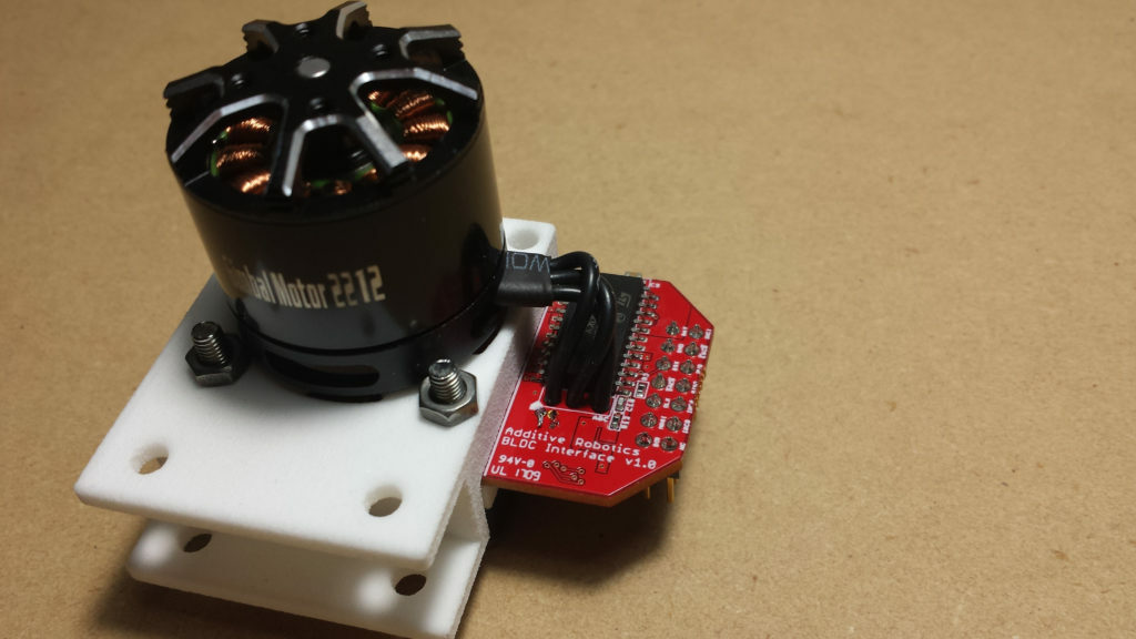
A small fan, powered by the on-board regulator and mounted behind the board, pushes air through the holes and into the motor mounted in front of the board. This allows a single fan to cool a small motor and the driver circuitry at the same time. The cooling is important because it increases the power density of the actuation system, by increasing the maximum current the motor can handle without overheating. The system is also very flexible in terms of motor selection; you can use any brushless motor as long as you can attach a magnet to the shaft and align it with the crosshairs on the board.
Many thanks to Josh with Additive Robotics for providing us with thorough details and additional photos!
Did you enjoy this post or find it helpful? Let us know in the comments below!