Integrating the Arduino Platform into Your Product: Key Parts
The Arduino platform is one of the most widely used hardware and software environments for developing and prototyping new products. Using various shields and breadboard techniques, the Arduino platform allows for fast prototyping. However, using an Arduino development board in your finalized product is far from ideal. This article will break down the Arduino Uno schematic and go over how to integrate the hardware into your new product directly.
Dissecting the Arduino Uno: A Component-Level Breakdown
Below is the Arduino Uno reference design which can be found on Arduino’s website.
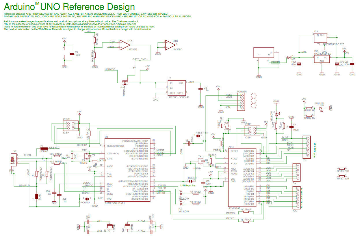
Arduino Uno Reference Design
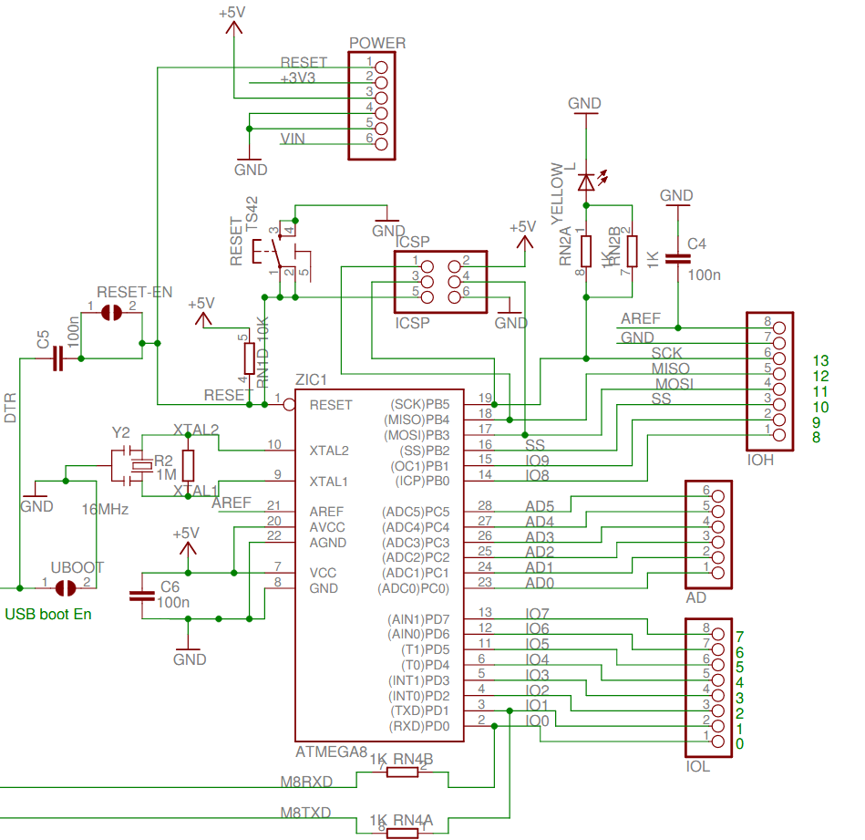
The Heart of Arduino: The ATmega328P Microcontroller
When you upload a sketch or compiled program to the Arduino Uno this is the part that is getting programmed. The ATmega328P-PU has been the core of the Arduino hardware platform since the very beginning. Here the ATmega328P-PU is basically pined out to headers, has its ICSP (more on this later) port exposed, a 16MHz crystal, and the power bypass capacitors.
Arduino Uno AT Mega328 P
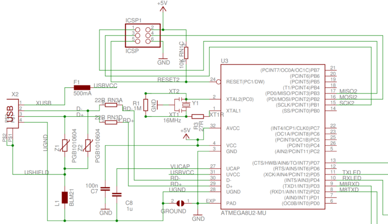
Connecting Your Arduino to the World: The USB Interface
Arduino decided to roll their own USB to Serial bridge on the Uno by using an ATmega8U2-MU microcontroller. The ATmega8U2-MU has dedicated USB hardware I/O but is limited in program and data memory size compared to the ATmega328P. All this part of the circuit does is take the differential signaling from the USB connection and convert it to a serial signal that the UART on the ATmega328P can understand.
Arduino Uno USB Interface 768x443
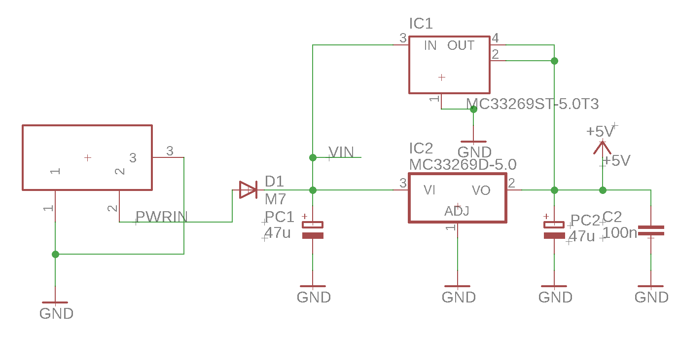
Powering Your Arduino: A Look at the Power Supply Circuit
The main power supply circuitry for the Arduino Uno is +5.0V DC as the ATmega328P-PU and ATmega8U2-MU require this to operate. Interestingly, the UNO has two MC33269 LDO regulators on the schematic, MC33269ST-5.0T3 and MC33269D-5.0. Why two LDOs? Well, a look at the Arduino Unos layout filein Eagle shows that IC1 and IC2 share the same footprint. This must have been done to document part substitutions if one of the packages was out of stock.
Arduino Uno LDO
Looking at the MC33269 datasheet shows something interesting about these part numbers. The MC33269ST-5.0T3 (IC1) is a SOT-223 package and fits on the footprint. The MC33269D-5.0 (IC2) is actually a SO-8 package and won’t fit on the footprint of the PCB. Assuming this is just a typo and not a wrong part number the MC33269DT-5.0 is a DPAK package that also fits on the footprint.
To prevent the DC jack from being wired up incorrectly, the diode at D1 provides reverse bias protection.
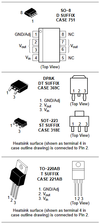
MC33269 Packages
Datasheet, above, showing the different packages for the MC33269 LDO voltage regulator.
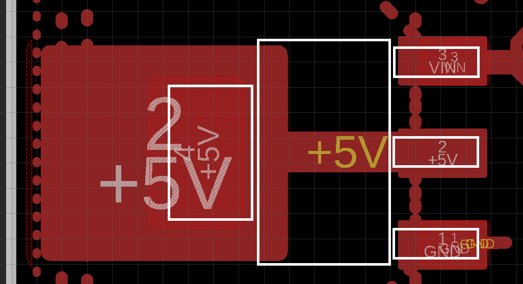
MC33269 ST
IC1 on the Arduino Uno Schematic, MC33269ST-5.0T3, overlayed on the PCB footprint.
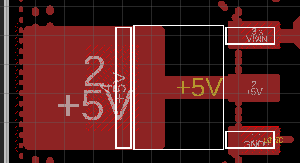
MC33269 DT
IC2 on the Arduino Uno Schematic, MC33269DT-5.0, overlayed on the PCB footprint.
For a +3.3V DC rail there is a LP2985-33DBVR LDO regulator. On the Arduino, this regulator’s sole purpose is to provide a reference voltage to the power switcher/muxing circuit. This does not take a lot of power to do so the majority of the regulators 150mA current capacity can be used for powering up small external circuits and sensors.
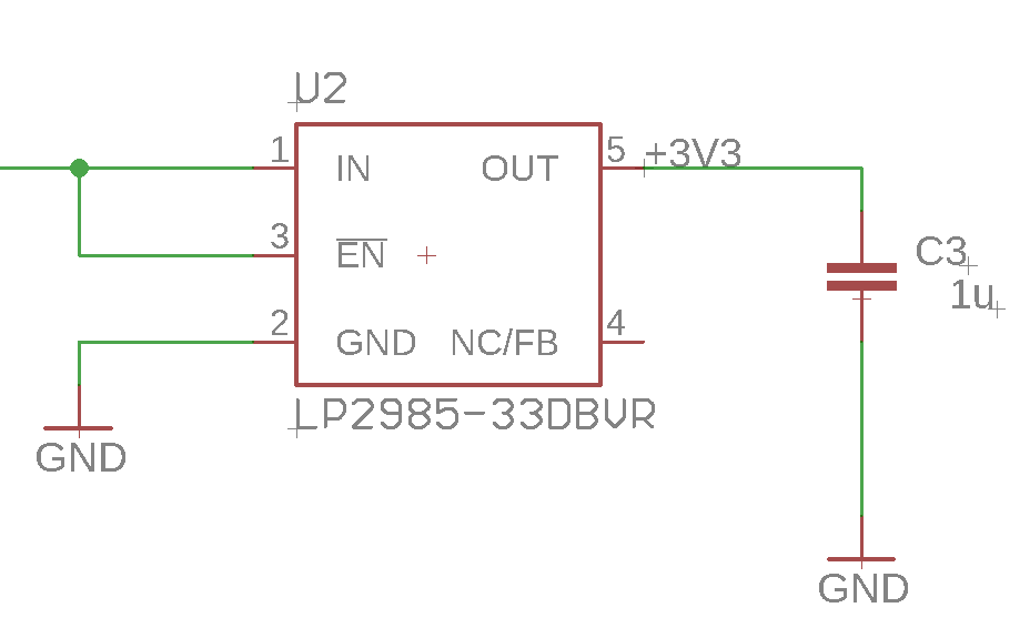
Arduino Uno 3 V3
Arduino Uno 3.3V LDO Power Circuit
Powering Your Arduino: The Power Switcher/Muxer Explained
This is the most interesting part of the Arduino Uno schematic. This circuit determines if the Arduino Uno is going to pull power from the DC jack or from the USB connector. I simplified and consolidated the original schematic into the schematic below.
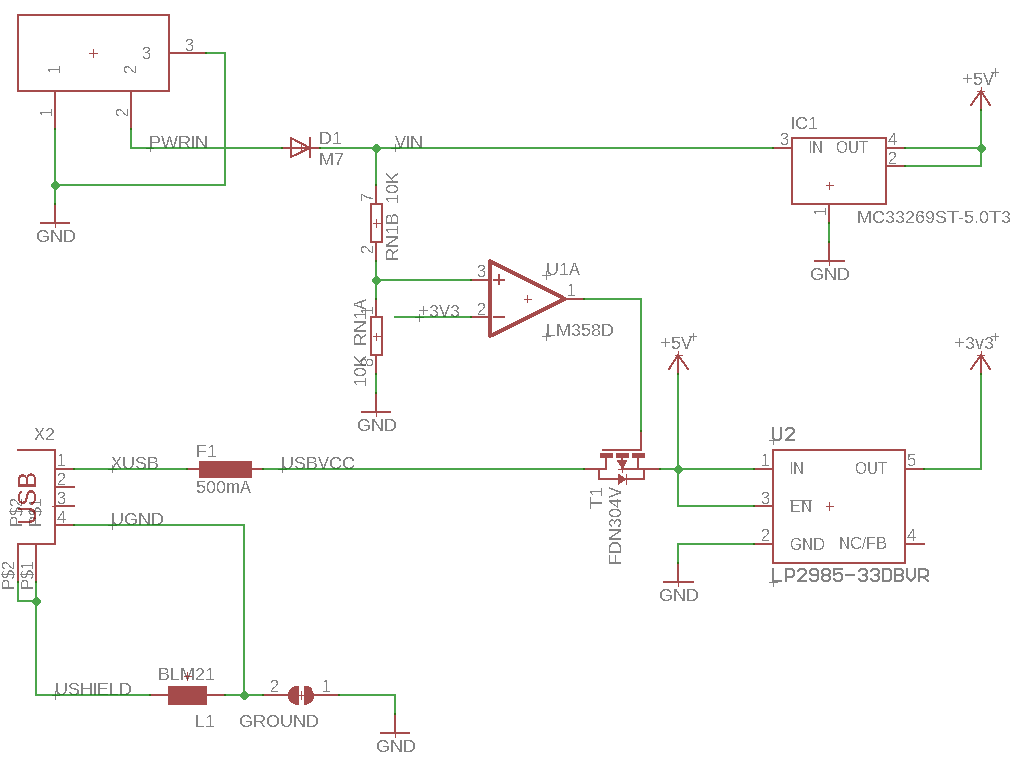
Arduino Uno Pwr Path
Arduino Uno Power Muxing Path
Powering the Arduino can happen in two different ways. One way is to provide the USB connector with +5.0V DC and the other way is to provide +7.0V DC to the DC jack.
If the USB connector is powered with +5.0V DC and the DC jack has less than +7.6V DC then the circuit works the following way.
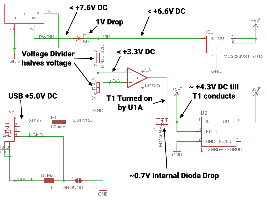
Arduino Uno Pwr Path USB PWR
Arduino Uno Power Path under USB Power
The internal diode in the T1 P-channel MOSFET drops the voltage to ~ +4.3V DC. This ~ +4.3V allows the LP2985 (U2) to output +3.3V since it has an ultra-low drop out of 7mV at a low current. This also turns on the LM358D (UA1) opamp. This opamp is set up as a comparator. Since the voltage from the DC jack is below the cutoff set by the voltage divider (RN1B and RN1A) and the +3.3V power line, the LM358D drives the gate on T1 low which allows current to flow and raises the ~ +4.3V DC coming out of T1 to closer to +5.0V DC.
If the voltage on the DC Jack is greater then +7.6V DC then the circuit works the following way.
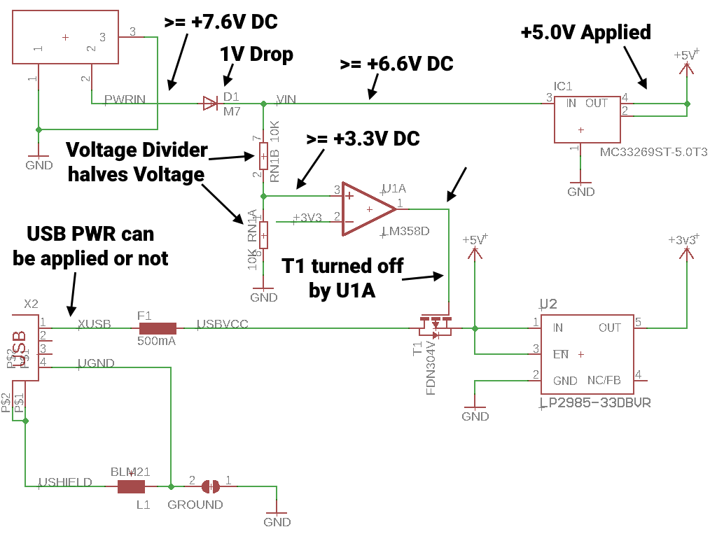
Arduino Uno Pwr Path DC PWR
Arduino Uno Power Path under DC Jack Power
The +7.6V or greater voltage loses 1V due to the diode D1. This reduced voltage then goes into the MC33269 (IC1 or IC2) voltage regulator and applies +5.0V to the power rail. This powers up the LP2985 (U2) to supply the +3.3V DC rail. The voltage divider (RN1B and RN1A) halves the DC power input voltage to greater than or equal to +3.3V. The LM358 (U1A) then drives the gate on the T1 p-channel MOSFET high which closes the MOSFET and prevents back-feeding the USB connector.
Programming Your Arduino: Understanding ICSP
In the case of the Atmel microcontroller (or now Micromel microcontrollers), ICSP stands for In-Circuit Serial Programming also known as ISP. This is a different way to program the microcontroller than the way Arduino programs. ICSP uses external hardware (an ICSP programmer) to communicate to the microcontroller and load compiled code. Arduino uses the USB interface and a small program that runs at startup on the ATmega328P called the bootloader. This bootloader looks for serial data coming over the USB to the serial bridge. If it sees the correct data it will then load it into its program space.
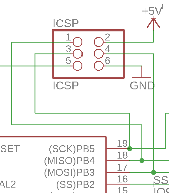
Arduino Uno ICSP e1528228828715
Arduino Uno In Circuit Serial Programming Interface
Using the ICSP interface to program your Arduino or ATmega328P you can load different Arduino bootloaders or remove them altogether to gain more program space.
Why Integrate Arduino Components into Your Product?
There are three main reasons to integrate the Arduino board you are using to prototype into your product directly.
Reduce Production Costs
Official Arduinos are pricey and the clones still cost more than just a bare ATmega328. Having to add through-hole headers to your PCB to connect to the Arduino like a shieldalso raises the cost. There is also additional assembly time needed to assemble your stack up inside your product.
Simplify your Supply Chain
Removing the Arduino will reduce the complexity of your supply chain. Instead of having to source the Arduino, you can just order the ATmega328P directly from the supplier of all the other electrical components you are using for your product. An unlikely (in the near future) but the real scenario could be if Arduino phased out the Arduino UNO that you use for your product.
Reduce the Size of your Product
This in my opinion is the most important reason to integrate the hardware into your product directly. The headers and shield nature of the Arduino platform make for bulky PCB stackups. Integrating the hardware will allow you to get your product down to a single PCB in most cases which will reduce the overall size of your product.
Minimal Hardware Needed to get the ATmega328P running
Ok, we are going to integrate the Arduino into our product. To start we should look at what it takes to get a stand-alone ATmega328P running. Assuming you are providing the +5.0V DC power already you only need the following 5 parts.
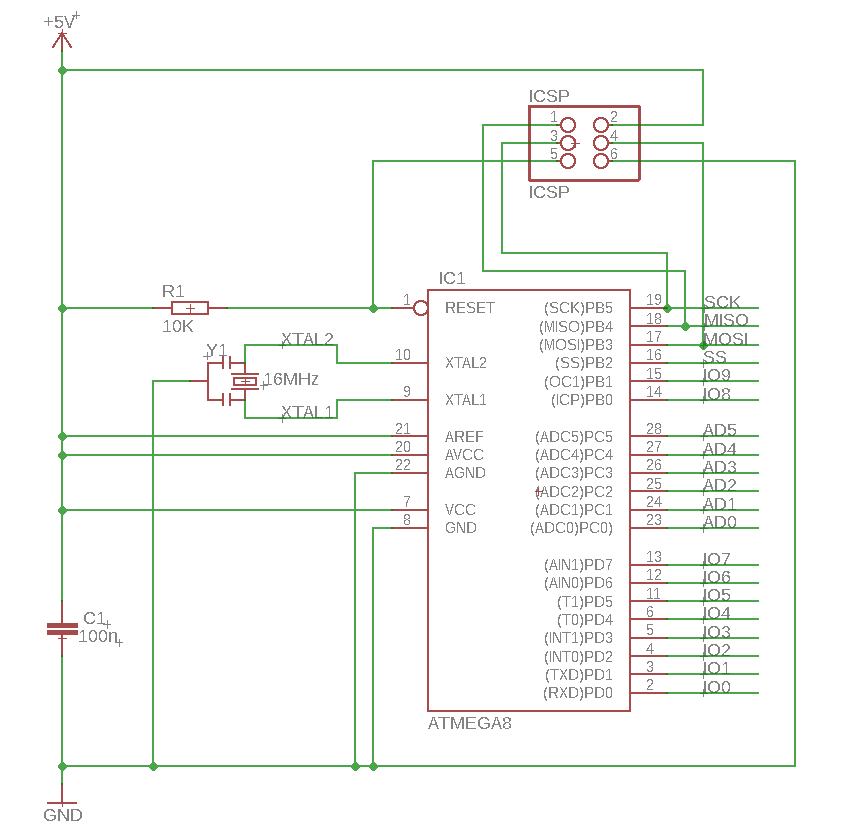
Just 328 P
- IC1 – ATmega328P-PU
- This is the IC that is being programmed when you upload your Arduino Sketch
- Main microcontroller for your project
- R1 – 10K resistor
- This resistor pulls the Reset line on the ATmega328P high
- Keeps the ATmega328P from randomly resetting during code execution
- C1 – 100nF capacitor (ceramic type)
- Bypass capacitor to provide localized power smoothing
- For more information on why bypass capacitors are needed see Dave Jone’s great video on them
- Y1 – 16MHz crystal
- Provides a reference frequency for the ATmega328P to operate at
- Not strictly 100% necessary as the ATmega328P has an internal oscillator but for any projects that involve any kind of timekeeping and communication this is needed
- If you want to learn how to run the ATmega328P without an external crystal take a look here.
- Depending on the crystal selected you may need to install loading capacitors from the XTAL1 and XTAL2 lines to ground, these can range from 4pF to 30pF in value
- ISCP – Programming port
- Needed to provide a connection to an ISCP Programmer
Does Your Product Need USB Connectivity?
If your product uses USB for communication consider using the following dedicated USB serial bridge ICs: FT230X, CP2102. These ICs are less expensive than the ATmega8U2-MU microcontroller that the Arduino uses for USB to UART and typically do not need any configuration or programming to get working.
Another solution is to prototype with a USB Native Arduino board like the Leonardo. The Arduino Leonardo uses an ATmega32U4. A consideration before making this change however is that the ATmega32U4 microcontroller has slightly less program space and ram compared to the ATmega328P when the bootloader is installed. This is due to the USB programming stack in the Leonardo’s bootloader taking up more space.
Choosing the Right Package: DIP vs. SMT
The ATmega328P-PU is the DIP or through-hole version of the IC. Atmel makes the ATmega328P-AU which is the QFN surface mount part. The AU part is slightly cheaper per unit, will be much less expensive to assemble, and takes up less board real estate than the PU part. Definitely consider switching to this flavor of the ATmega328P when integrating Arduino. As a bonus, the AU also has two extra I/O pins that the Arduino software supports. There is also an Arduino UNO SMT version but it does not break out these two extra I/O pins.
Streamlining Power Delivery: A Simplified Approach
Most products only have one way to power the device. If you are a strictly USB-powered device you do not need to use the power switcher/muxing circuit. Devices that are powered by replaceable batteries do not have to worry about this as well. Devices using internal rechargeable batteries like lithium will need a way to charge the device and operate at the same time. There are lots of different single IC solutions for this but I have personally used the Ti BQ24075RGTT in the past and it works well.
Programming Your Arduino: ICSP Explained
Does your product even need the Arduino bootloader? The bootloader allows easier programming over USB instead of having to use an ICSP programmer. If your device is not intended to have firmware updates in the field then you will not need the bootloader.
I always recommend designing your product to be programmed in the factory by ICSP as it tends to be faster and more reliable. When you use the Arduino IDE to “Upload” the file it actually recompiles the software every time which is fairly slow. You can use the ICSP header and programmer to pull an “image” of the hex file off the ATmega328P and then use this image to program all your production devices over ICSP.
To reduce your number of line items and assembly costs consider using a programming cable like tag-connect.
Listen to this classic Circuit Break Podcast episode to learn even more about Arduino.
Key Takeaways: A Recap of Arduino Integration
That should complete the breakdown and explanation of the Arduino UNO hardware. If you want more information about designing and building an ATmega328P-AU (SMT version) based development board that uses tag-connect check out the article Getting started with Tag-Connect on an AVR MCU. Also, check out the Macro Duino which is a Duino compatible development board I developed that uses an FT230X for the USB UART bridge and a USB Type-C connector.
The Macro Duino was discussed on podcast episodes MEP EP#31: Embedded Brewing with Arduinos, MEP EP#35: Surgical Synthesizers, MEP EP#36: Cloud Net, MEP EP#37: Banned Arduinos and Tuning Software By Ear, and MEP EP#40: Update on the MacroDuino and FX DEV Board so go give those a listen.
Related Topics
EMS 2.0 Digital Electronics Manufacturing Transformation
If you’re a supply chain professional, engineer or business owner this webinar will show you how you can access an agile digital platform that brings the
Proper Prototyping Practices for Product Development
Proper prototyping for product development can help your NPI get to market faster. Here are some guidelines to help ease this process.
Top 6 Mistakes to Avoid in High Volume Electronics Manufacturing
High volume electronics manufacturing requires careful planning and organization. Here are the top six stumbling blocks to timely production.
About MacroFab
MacroFab offers comprehensive manufacturing solutions, from your smallest prototyping orders to your largest production needs. Our factory network locations are strategically located across North America, ensuring that we have the flexibility to provide capacity when and where you need it most.
Experience the future of EMS manufacturing with our state-of-the-art technology platform and cutting-edge digital supply chain solutions. At MacroFab, we ensure that your electronics are produced faster, more efficiently, and with fewer logistic problems than ever before.
Take advantage of AI-enabled sourcing opportunities and employ expert teams who are connected through a user-friendly technology platform. Discover how streamlined electronics manufacturing can benefit your business by contacting us today.