This is the fourth and last article in the PCM5122 DAC PCB series. Here is a recap of the previous articles in the PCM5122 DAC series.
- 3 Steps to Planning Parts Selection for Your Next Electronic Hardware Product
- Designed the PCM5122 DAC PCB
- Used the MacroFab platform to design three different Bill of Material load outs of varying pricing
- Test results of the PCM5122 Audio DACs
- Built three DACs with different Bill of Material load outs
- Tested the DACs to see which one performed better
- Did a blind audio listening test to see if people preferred a specific load out
- Setting Up Production Testing for the PCM5122 Audio DAC
- Designed a test fixture for the DAC PCB
- Modified the DAC PCB to add pogo pin contacts
Completed Test Fixture
This is the completed fixture with the 3D printed standoff attached. The 3D printed standoff aligns the PCB to be tested over the pogo pins and also protects the pogo pins from damage. Power is provided by the Arduino Zero via a micro USB cable.
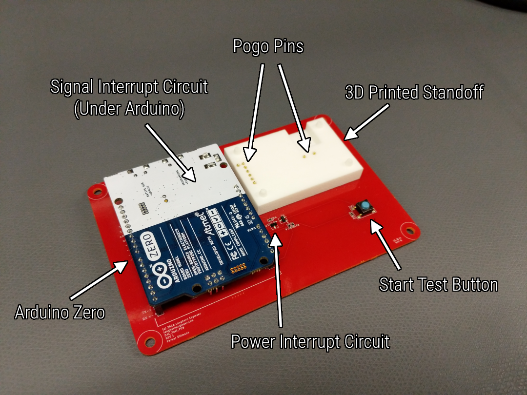
The completed DAC Fixture with 3D printed standoff attached.
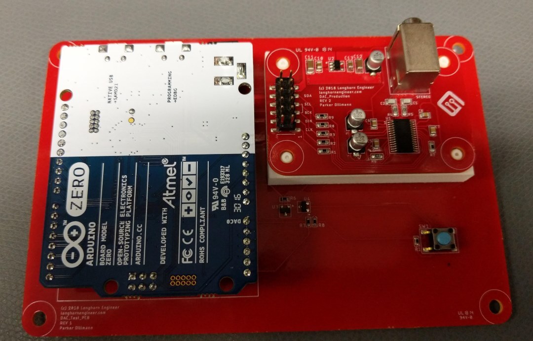
Fixture with the DAC PCB ready to be tested.
Code Theory
I used the Arduino IDE to develop the code the the fixture. This was done to minimize development time. Special Thanks to the following for having awesome sample code and Arduino Libraries that made this doable!
- avdweb: For the super fast AnalogRead Function
- Adafruit: For the FFT library that runs on the Arduino Zero. I would not want to code this myself
- Théo Meyer: For the Zerodio Library where I was able to figure out how the TC5 Interrupt functioned on the Arduino Zero
Here is the theory of operation on how the code works.
- Wait for button press
- Establish I2C connection with PCM5122 PCB
- Configure the PCM5122 over I2C
- Setup TC5 to push a 200Hz signal at 8000Hz sampling over I2S
- Record the output of the PCM5122 with analog input
- Run FFT and analyze the signal
- Notify user over Serial if the PCM5122 PCB passes the test
- Repeat with next PCM5122 PCB
Using the Test Fixture
The fixture and test procedure is designed to be as fast as possible to reduce labor expenses. Setup of the fixture requires a micro usb cable and a terminal on the PC. Currently, I am using the built in Arduino terminal as it seems to work fairly well. An untested DAC PCB is then placed on the 3D printed stand off area and then slight pressure is applied. The 3D printed stand off allows the board to self center on the pogo pins. Once the DAC PCB is in place, the operator presses the start test button. This kicks off the test procedure and after the tests are complete the terminal displays the results of the test. If the DAC PCB is good we get a “Unit Passes.”!

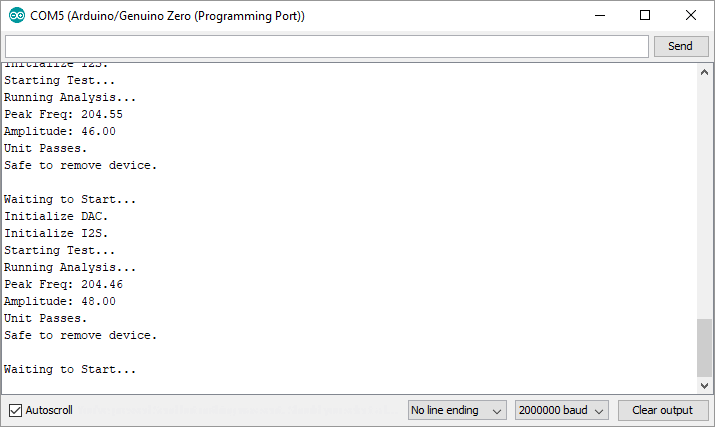
Arduino Serial terminal displaying the test results of a DAC PCB.
Files For The Project
If you would like to take a look at the files for the PCM5122 DAC Board, Fixture PCB, Fixture Mount, and software I uploaded them to the MacroFab Github Repo. Feel free to replicate or expand on the project. PCB board files are in Eagle, Fixture Mount was designed in SketchUp, and the software was coded in the Arduino IDE.
MacroFab/Macro_Articles/PCM5122_DAC
Recap
This article will conclude the PCM5122 DAC series of articles. We started with prototyping and designing a PCB, went through testing, and finished up with a production ready PCB and test procedure. I hope that this series of articles is useful to beginners looking to build their first product and go to production with it. Having a well defined test procedure and reliable fixture for the test is just as important as designing the product itself. As you design your next product take a look at designing for testability (DFT) and see how you can reduce the time and effort required to test the product.
Was this post helpful? Have other questions? Let us know in the comments below.