PCB Programming for assemblies during production is a common topic we’re asked about at MacroFab. There are a couple of different ways to go about programming a device after production and it mainly depends on the volume of the assembly run and the form factor of your device. These methods have their own pros and cons, but should be taken into account early in the PCB design process.
Programming ICs: From the Factory
The first method and possibly the easiest is to get your ICs preprogrammed from either the manufacturer or through the distributor for the parts. Both Mouser and Digi-Key offer low-cost programming as an add-on service.
With the ICs preprogrammed you can skip the programming fee of the assembly house. It also removes the need to include a programming connector or footprint in your board design, which enables lower-cost manufacturing and a smaller product.
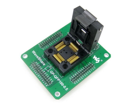
This works by placing the IC inside a ZIF (Zero Insertion Force) socket (See Figure 1). The ZIF socket is connected to the ICs appropriate programme and support circuitry to make it function. The IC is then programmed and repackaged for assembly.
The downside to preprogramming is if there is a firmware bug or feature change, and you need to push an update mid-production, you are out of luck and would have to reprogram all your ICs.
If you opt to remove any kind of programming header, then rework will be needed on the PCBs to remove the chips with faulty code. This is the least flexible option for programming your assembled circuit boards. There is usually a setup fee from the manufacturer or distributor along with a per-unit charge. This method works great for programming bootloaders as these seldom change.
Programming PCBs: Dedicated Headers
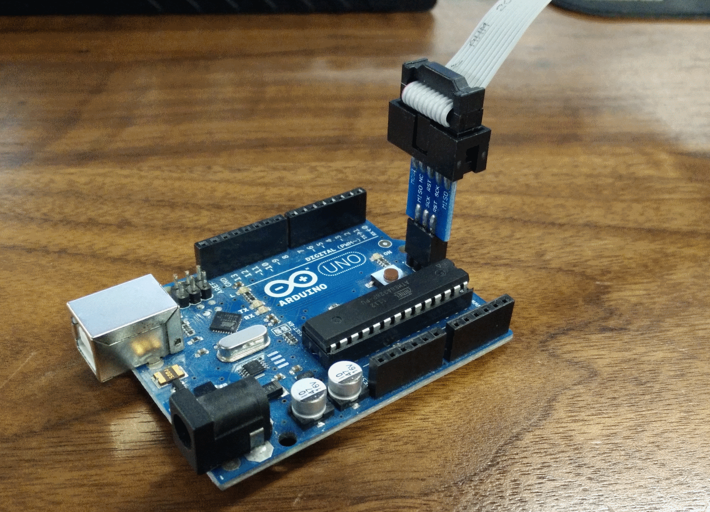
Dedicated programming headers are probably the most common way to program devices. This enables an easy connection to the program and allows the end-user to change the software easily.
The only downside to this method is the added cost of the connector part and assembly of that part. Connectors are usually one of the more expensive items to assemble on a PCB so reducing these is usually ideal for any kind of production run. If your connector isn’t keyed, you could also run into issues with connectors being plugged in backward resulting in a false negative on the programming and testing.
Other connectors that fall into this class would be USB connectors. Programming over USB for production is generally fine and repeatable.
Programming PCBs: Manufacturing and Test Jigs
For higher volume runs, a programming jig can be designed using pogo pins.
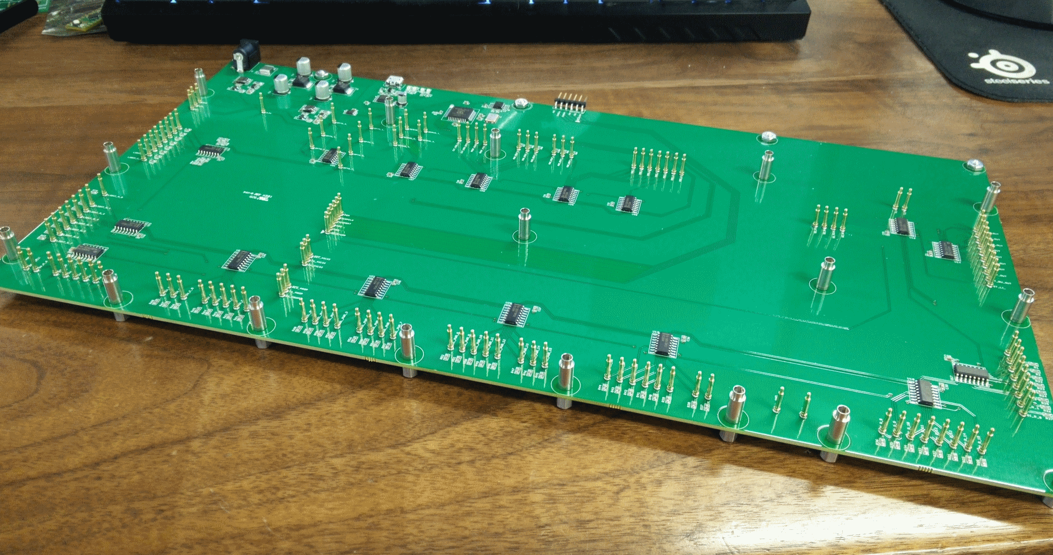
Pogo pins are spring-loaded contacts that make electrical connections between PCBs. With these, you can press into contacts on the PCB you want to program. Figure 3 has the programming and test jig for the Pinheck Pinball System. This jig does more than just program, it also tests all the various functions of the PCB. The Pinheck Pinball PCB sits on the standoffs and slightly compresses the pogo pins in Figure 4.
Learn about designing and building a pogo pin programming fixture now.
Programming jigs can be set up to program entire panels at once, which greatly speeds up production and testing.
The downside to programming jigs is that they are sometimes expensive to develop and build. This leads them to only be used for medium to high volume runs to help spread out the tooling cost.
Programming PCBs: Universal Headers
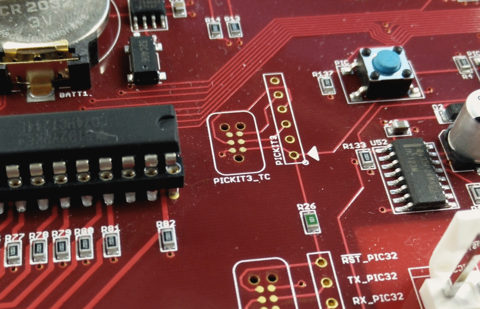
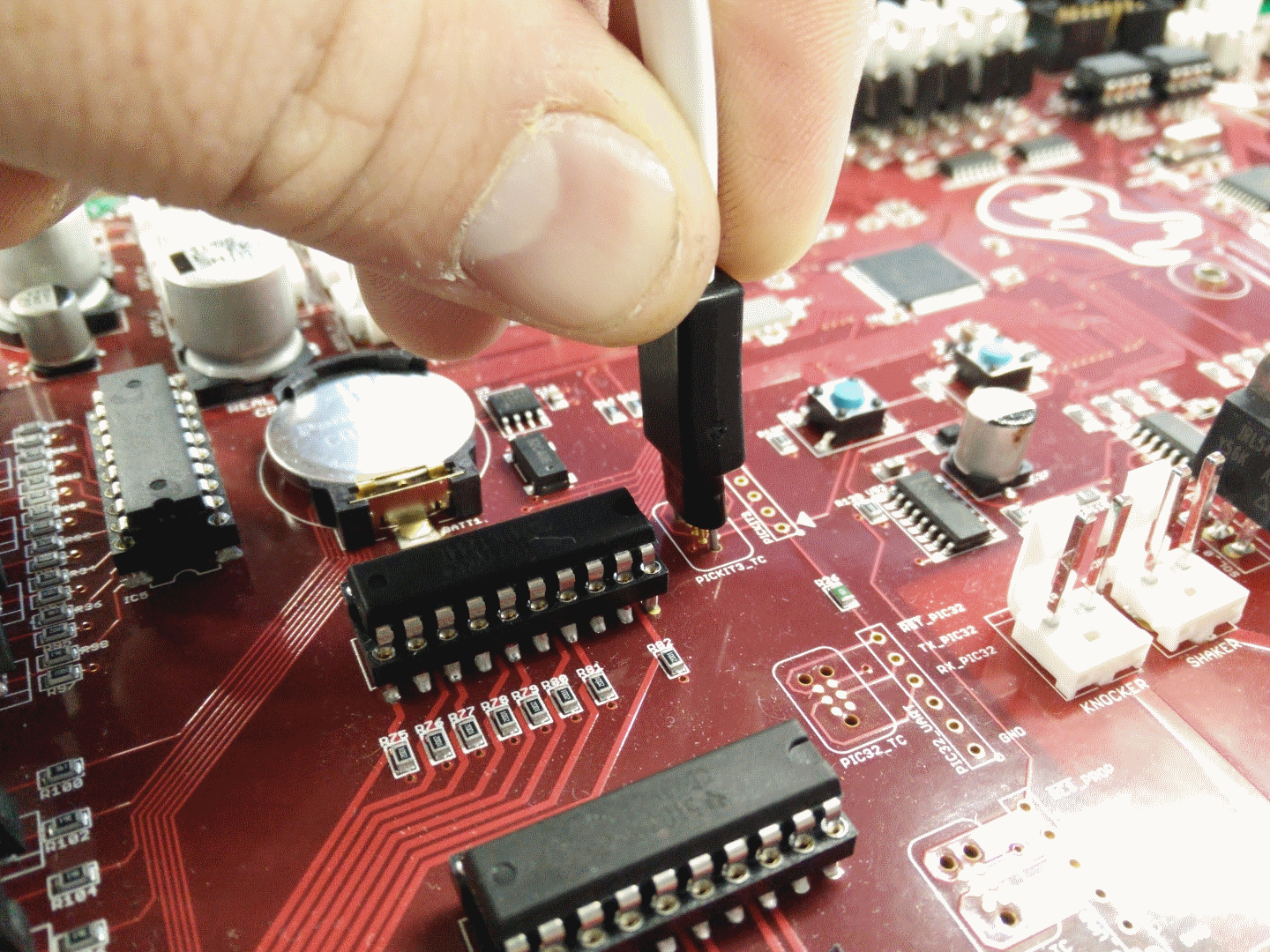
Another option is somewhat in between dedicated programming headers and pogo pin jigs. Tag-Connect makes cables that have built-in pogo pins. One end is connected to the specific programme and the other end presses into the PCB contacts.
Other companies make similar devices like Sparkfun’s ISP Pogo Adapter. This style of a programming interface is great for low and medium volume as it removes the need for a dedicated header and the need to build an expensive programming jig.
Ready to start your next project with greater agility and transparency?