The design for the SSPS has come a long way since the last SSPS blog post. We have created the first functioning prototype of the system and have begun running tests. In this post we will take a look at the prototype and see some initial performance tests.
The Prototype
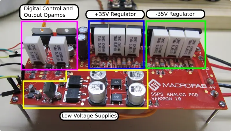
At the heart of the prototype is a test PCB that contains the full functionality of a single output channel. Included on this PCB are the following sections:
- +/- 35V high current regulators
- +/-15V supplies for powering analog portion of the test
- +3.3V for digital controls
- Two 16-bit DACs for controlling the output voltage
- Two OPA541 opamps
- 16-bit ADC along with a precision differential amplifier for measuring the output current
Here is an image of the PCB showing the major sections:
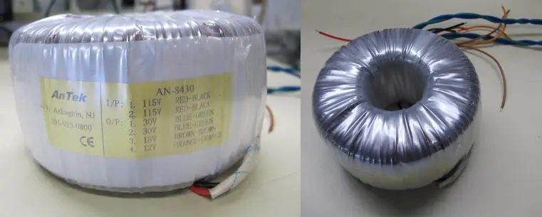
Since the output of the SSPS is high voltage ranging from -35V to +35V our test setup would need to be powered by a source that can handle these voltages. The bench power supply we us (Rigol DP832) can only output +/-30V so unfortunately we could not use this as our main power source. To get around this we decided to simply hook up the main power transformer that is intended to be used in the final version of the SSPS. This transformer has two 30V taps that can source 13 amps each. After rectification they produce 43V – perfect to power the prototype.
In order to produce the two separate 43V power rails we need to rectify and smooth the power from the transformer. In previous posts, we have discussed the design of the “Energon Cube” -the name that we have given to the assembly of the capacitor bank and PCB for the output of the SSPS. Here is a concept drawing and an exploded view of the assembly:
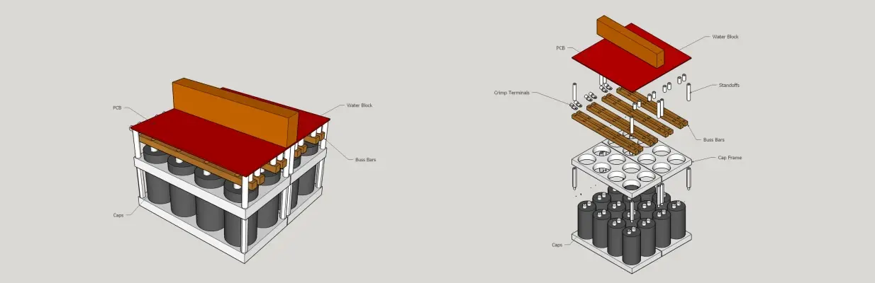
In the base of the energon cube are a bank of capacitors that are used to smooth the power from the main transformer. For our prototype we created a mock up of this capacitor bank.
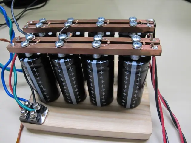
The capacitors used in this bank are screw terminal types. To connect the caps together we cut short lengths of 5/16″ x 5/16″ copper buss bars and screwed them directly into the capacitor terminals. Bleeder resistors were connected across the terminals to help discharge the capacitor banks when not energized. The rectifiers chosen for this circuit also have screw terminal connections so that the transformer leads could be screwed directly to the component.
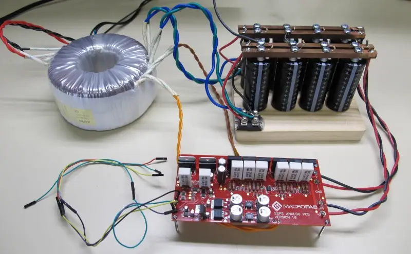
Here is an image of the whole prototype setup:
Testing
Upon the first power-up, various voltages including the input power rails, the regulator outputs, the low voltage power supplies, and the opamp output to ensure that the circuit was responding according to the design. Luckily, all of the voltages measured within the expected ranges.
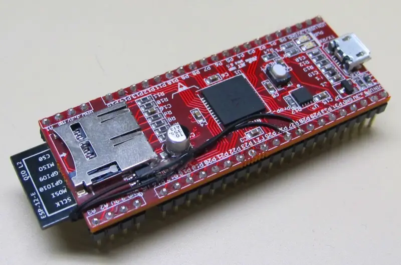
The output of the power supply is controlled by two separate 16-bit digital to analog converters. One of the converters controls positive output voltages from the supply and the other converter controls negative. Setting the power supply to output a particular value is as simple as writing a 16-bit number to one of the DACs using an I2C protocol bus. To do this we programmed a Parallax Propeller development bit flicker (designed by Parker Dillmann here at MacroFab) to output I2C data directly to the SSPS PCB.
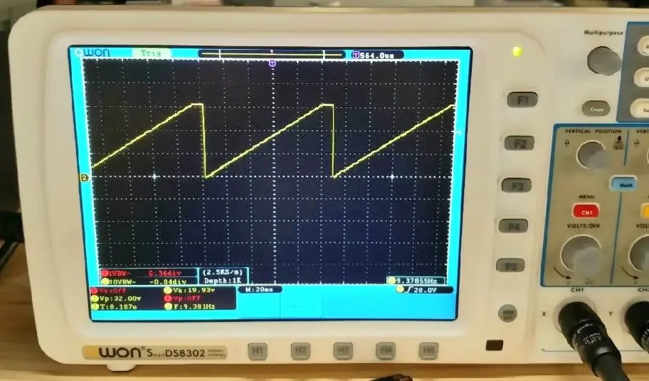
The first program we ran wrote increasing values from 0 to 65535 continuously to create a ramp wave that varies from 0 volts to the maximum output voltage (about 33 volts). Here is an image that we took of the resulting waveform on our oscilloscope:
There is a small portion of the wave that is flat near the top of each ramp. This was due to some calibration offset in the design that will be adjusted.
The first round of testing on the board was a great success and the circuit is behaving as we would expect it to.
What Comes Next
Although the initial tests were a success, there is ton of tests we need to complete before moving onto the next revision. A few examples of these tests include:
- Load Testing – Observing performance over a range of output loads
- Output Resolution – Measuring the minimum output change for a one bit change
- Stability – Ensuring that the power supply does not oscillate
- Repeatability – Measuring the ability of the supply to continually output a single voltage
- Thermal – Measuring the heat dissipation under load.
If you would like to check out our design files you can find them on our Github.