Conception
Here in the engineering department at MacroFab we are constantly coming up with ideas for projects ranging from binary watches to electronic noise boxes to custom PLC controllers. As our projects grow in complexity, so does our need for gear to test the designs. Our engineering department already has a well-stocked test bench with all of the standard test equipment you would see in a typical lab, but just like every engineer we are looking to acquire more and better gear.
In our discussions of what projects we would like to see in the future, we mentioned creating a simple power supply to have accessible at our desks. After adding feature after feature that we would like to see in a power supply, the initial design ended up being anything from simple. Some of the features we came up with included: power output in the hundreds of watts at high voltage, multiple isolated and independent outputs, digital control, and switchable DC and AC output. In the end we settled on the following wish list for the supply:
- Two isolated -30V to +30V @ 10A outputs
- Full digital control of each output with a resolution of 10mV per bit
- Current limiting
- DC and AC output capability
- Rack mounted case
We gave the title of the project the Super Simple Power Supply or SSPS for short even though there really isn’t anything simple about it.
Design
Since Parker (the head of engineering here) is predominantly a digital electronics designer and I am an analog guy we decided to split the project in two and tackle the two realms separately. While looking for a way to provide the large amount of output power, we stumbled across a powerful opamp that appears like it can handle the task with a very simple circuit. This opamp is the OPA541 from Texas Instruments.
Here is an image from the first page of the datasheet:
This opamp has the capability to be powered off of +/-40V rails and output a continuous 5 amps (provided the device remains within the safe operating area as defined on pages 6-7 of the datasheet) and it comes in a small T0-220 11-pin package. The datasheet even states in its application section that this device can be used for programmable power supplies. It looks like this device may be the ticket to a simple and easy design.
We have never really thought of opamps as devices capable of delivering large amounts of power as most opamps have a maximum output of around 25mA. The OPA541 however is an absolute beast in terms of its features. Basically, it is a standard opamp on steroids.
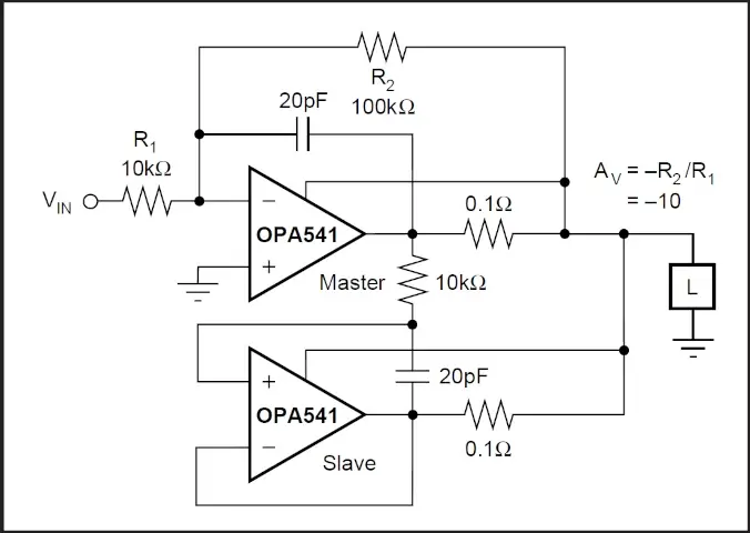
Even though this opamp has impressive features, it still lacks the full 10A output current that we have specified in our wish list. We are in luck though because there is a nifty little trick we can do to put these opamps in parallel for higher output current. Page 7 of the datasheet gives an example circuit shown here.
In this circuit, we basically have a standard inverting gain stage with a voltage follower on the output. The voltage follower mirrors the output of the master opamp effectively doubling the output capacity of the circuit.
It looks like we have the beginnings of what could work for our power supply output.
Listen to this classic Circuit Break Episode to hear Stephen and Parker reminisce about building trebuchets and talk about A/C control module schematics, including an op-amp comparator circuit.
Simulation
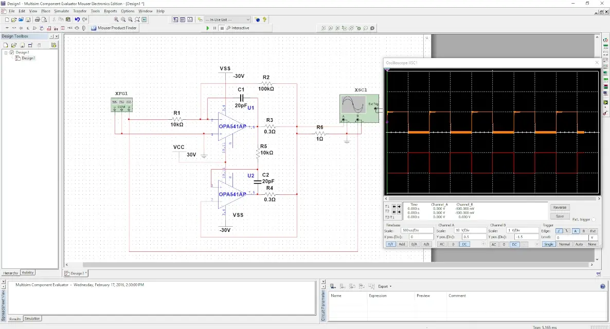
To test the circuit above we simulated it in MultiSIM BLUE. MultiSIM BLUE has the capability to access a Mouser database of parts and a spice model of the OPA541 was readily available. Here is a screenshot of the simulation.
The circuit has a gain of 10 due to the resistances of R2 and R1 so we input a square wave of 1Vp-p which should result in an output of 10Vp-p. The output load was set to 1 ohm to test the full output current of 10A.
The results of the simulation showed that the opamps had no issues with dumping 10A into the 1 ohm load.
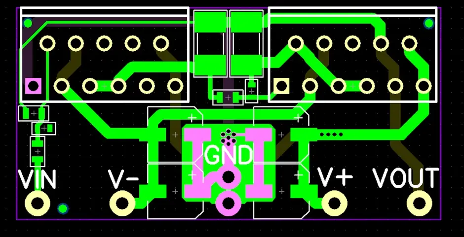
PCB
The next step was to transfer this design to a breakout PCB to do some real world testing. We used Diptrace to layout a small 2″x1″ board that we could use for bench testing. The circuit was identical to the one used in the simulation except we added some local bulk capacitors on the power rails to help smooth out any ripple.
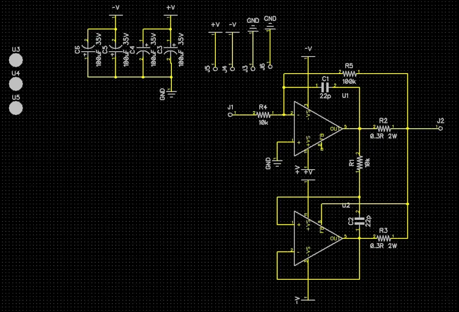
Here are some images of the schematic and layout.
Since the engineering department has the luxury of sitting just feet away from a PCB manufacturing outfit we were able to have the boards assembled quickly. Here is an image of the populated PCB.
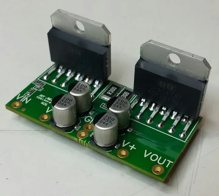
Testing
The beauty of this breakout board is that there are only 5 connections needed for testing. Just connect +/- power, ground, and an input signal and testing can begin.
We began by powering the breakout board with +/-30V and injecting a 1Vp-p 1Khz square wave just as was done in the simulation. For this initial test we did not connect a load to the board other than our oscilloscope probes. To be expected, the circuit pumped out a 10Vp-p signal just as in the simulation.
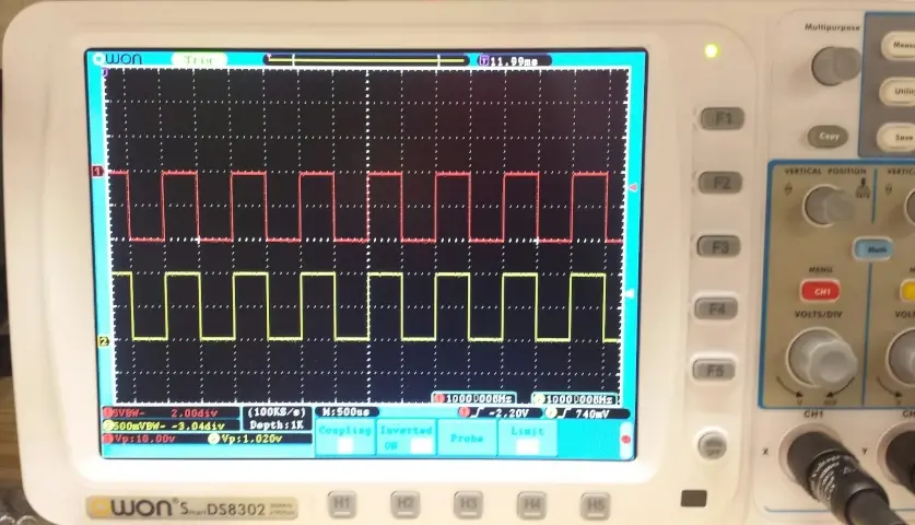
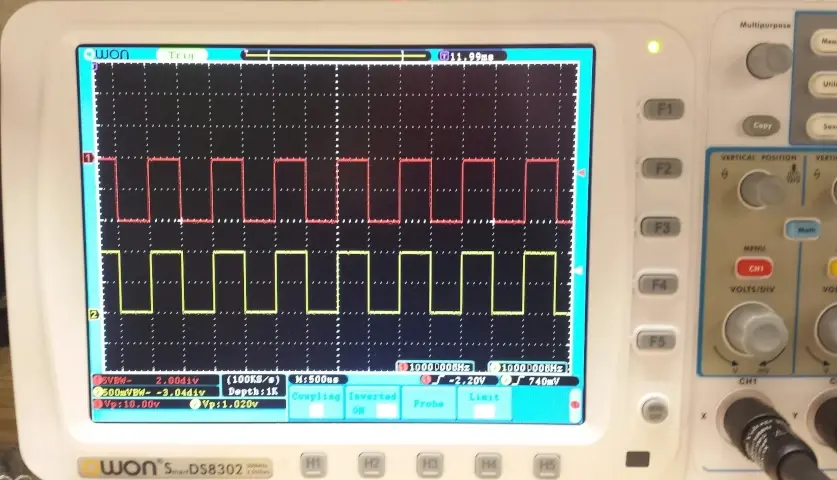
Now that we know the opamps are doing what they should we moved to a heavier test. We had a big 200 watt power resistor lying around that could act as a pretty hefty load.
With a 10Vp-p output, we could expect 10/8 = 1.25 amps. Since we were injecting a square wave, this 1.25 amp load would only draw when the signal goes high so the average current from the output would be around 0.625 amps. This is not near the 10 amp max current that the circuit is supposed to be able to source, but it makes for a good initial load test.
Here is an oscilloscope image of the results.
Next Steps
More testing is required to validate the use of the OPA541, but at first glance, things are looking promising. In the next part, we will look at the big issue of handling the heat these opamps produce. We will be keeping the project up to date on our GitHub repository. You can find the files for the simulations, schematics, board layouts, and test results.