Optimizing Diode Functionality: Forward and Reverse Bias
Checkpoint
Understanding different modes of diode operation can be critical for designing and implementing electronic systems.
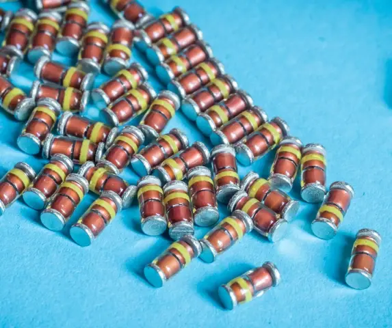
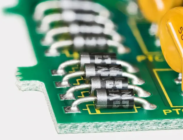
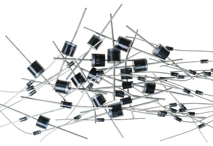
A diode is a fundamental building block in electronic systems and is used in a wide range of applications. Many thousands of diodes are embedded within integrated circuits to control logic and signals within a system on a chip. However, discrete diodes can also be used at the PCB component level for specific applications.
Despite their simplicity, diodes do have specific use-case scenarios that require a detailed understanding of their electrical behavior to maximize their utility within an electrical system. A fundamental understanding of diodes is gained by reviewing their two main operations: forward bias and reverse bias. It is crucial to understand the differences between these operations to choose the best diode for a particular application.
What is Diode Bias? Biasing Conditions
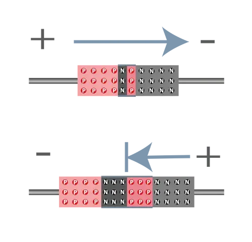
A diode is a two-node device that is non-linear, meaning its electrical behavior varies depending on the voltage applied across its two terminals, the anode and cathode. This non-linear behavior leads to two distinct operative modes, forward bias and reverse bias.
In forward bias, when the anode is connected to the positive voltage source and the cathode is connected to the negative voltage source, current flows through the diode, allowing it to act as a switch in electronic circuits.
In contrast, in reverse bias, when the anode is connected to the negative voltage source and the cathode to the positive voltage source, current is prevented from flowing through the diode, protecting electronic circuits from transient voltages.
Understanding different modes of diode operation can be critical for designing and implementing electronic systems. Diode bias should not change unexpectedly unless a catastrophic failure occurs. By design, the bias should be forward or reverse, and the diode application should match the expected bias.
What Diodes Can Do
In the forward bias mode, a diode operates with a nearly off state and passes very little to zero current when the applied voltage is below a specific threshold value known as the device’s Vt. A diode’s Vt characteristic is specific to its process and application and can be found in its datasheet. The Vt value is typically between 0.3V and 0.7V.
When the applied voltage is above Vt, the diode acts as a switch, allowing current to flow uniformly. When the applied voltage is greater than Vt in the forward bias mode, a current-limiting resistor is often used in series with the diode to prevent overheating.

The reverse bias mode is the opposite of the forward bias mode. When the voltage is applied in such a way that the negative terminal (cathode) has a higher voltage than the positive terminal (anode), it creates a reverse bias operation.
In this mode, when the applied voltage is below a specific threshold known as reverse voltage breakdown (Vbr), the diode allows very little to no current to flow. By increasing the voltage above Vbr, a reverse breakdown occurs, allowing current to flow in the opposite direction. Vbr is usually much larger in magnitude than Vt in forward bias mode, often between -15V and -20V.
Forward Bias vs. Reverse Bias
Diode functionality and forward bias
Diodes are typically designed to operate in the forward bias mode in electronic systems. There are various applications for using diodes in this mode, including
- suppressing transient signals
- clamping voltage
- rectifying AC/DC power
- steering current
- switching between two voltage sources
The light-emitting diode (LED) is another variation of a forward bias diode, which is commonly used as a red or green indicator in electronic applications. In most cases, diodes act as protection for signals, power domains, or grounds by limiting the voltage to no more than 0.3V to 0.7V above the intended operating maximum voltage.

Reverse bias and diode performance
The reverse bias diode largely prevents current flow until the large voltage potential of Vbr is reached. A specific type of intentional reverse bias diode is the Zener diode. This electronic component typically has a breakdown voltage near 5V to 6V, making it suitable for suppressing transients in power supply domains.
While the reverse bias mode can be used for regular diodes, the high breakdown voltage is typically outside the operating range required by most systems’ power supply domains.
Listen to Stephen talk about softness factor in diodes in this classic episode of Circuit Break.
What to Consider in Your PCBA Design
When designing your system circuit, it’s important to consider specific diode function. For example, if the diode will be used for protecting signals, power domains, or ground, transient voltage events will be suppressed with forward bias. It’s important to understand the non-linear behavior of the diode and how it will operate under both normal and excursion conditions.
Since the diode is non-linear, you must understand what system conditions will cause the current to flow when bias is above Vt and what conditions will cause the current to not flow when the bias is below Vt.
It’s important to note that different types of diodes have varying levels of voltage drop when in forward bias. For example, Schottky diodes have a low voltage drop of around 0.2 volts, while some LEDs may experience voltage drop of up to 4 volts. Excessive voltage drop can restrict the circuit and cause malfunctions.
Regardless of whether the current flow is in normal operating mode or during an excursion, you should simulate how the diode may inadvertently get turned off or on and operate outside intention. Conversely, the same conditions should be considered for the reverse bias and the Vbr voltage cases.
There are many practical use cases for a discrete diode or Zener diode in an electrical system design. First, consider the function required for the diode and how it will fit within the application. Second, determine the required bias for the diode, either forward or reverse. Last, test the use cases for proper operation and excursions that may change the bias of the diode or cause the current flow to change state.
Work with your contract manufacturer for diode selection for your BoM and additional use cases that may enhance your design performance.
FAQs
What is forward biasing a diode?
Forward bias is a way of connecting a diode that allows current to flow easily through it. In forward bias, the positive voltage source is connected to the anode (P-type) of the diode, and the negative voltage source is connected to the cathode (N-type). This connection pushes electrons in the N-type region and creates a force for "holes" in the P-type region to move in the opposite direction.
Despite not being actual physical holes, holes represent the absence of electrons in covalent bonds. This reduces the resistance within the diode and allows current to flow. Forward bias is commonly used in applications like rectification (converting AC to DC) and signal protection.
What's the difference between forward bias and reverse bias?
Forward bias and reverse bias are two opposite ways to connect a diode, leading to very different behaviors. As mentioned above, forward bias allows current to flow easily. In contrast, reverse bias blocks current flow.
During reverse bias, the positive voltage source is connected to the cathode, and the negative voltage source to the anode. This creates a barrier that hinders electrons and holes, stopping current flow through the diode. Reverse bias is useful for blocking unwanted currents and protecting circuits from voltage spikes.
When would I use forward bias vs. reverse bias in a circuit?
Diodes are typically designed to operate in forward bias mode for applications like rectification, voltage clamping, and current steering. However, there are specific uses for reverse bias as well. Zener diodes, for example, exploit reverse bias to regulate voltage by allowing current flow when a certain voltage threshold is reached. This helps protect circuits from voltage spikes.
Build from anywhere, anytime, with MacroFab.
Get an Instant Quote NowAbout MacroFab
MacroFab offers comprehensive manufacturing solutions, from your smallest prototyping orders to your largest production needs. Our factory network locations are strategically located across North America, ensuring that we have the flexibility to provide capacity when and where you need it most.
Experience the future of EMS manufacturing with our state-of-the-art technology platform and cutting-edge digital supply chain solutions. At MacroFab, we ensure that your electronics are produced faster, more efficiently, and with fewer logistic problems than ever before.
Take advantage of AI-enabled sourcing opportunities and employ expert teams who are connected through a user-friendly technology platform. Discover how streamlined electronics manufacturing can benefit your business by contacting us today.